Quick release folding propeller blades for a model aircraft

a model aircraft and propeller technology, applied in the direction of propellers, toys, transportation and packaging, etc., can solve the problems of conventional propellers generally requiring tools for the removal, or at the very least complicated manual operations

Active Publication Date: 2019-11-28
LANDING PROD INC
View PDF11 Cites 3 Cited by
  • Summary
  • Abstract
  • Description
  • Claims
  • Application Information

AI Technical Summary

Problems solved by technology

However, given the need to ensure that the blades of a propeller remain secured and operational during flight, conventional propellers generally require tools for the removal, or at the very least complicated manual operations.

Method used


Image

  • Quick release folding propeller blades for a model aircraft
  • Quick release folding propeller blades for a model aircraft
  • Quick release folding propeller blades for a model aircraft

Examples


Embodiment Construction

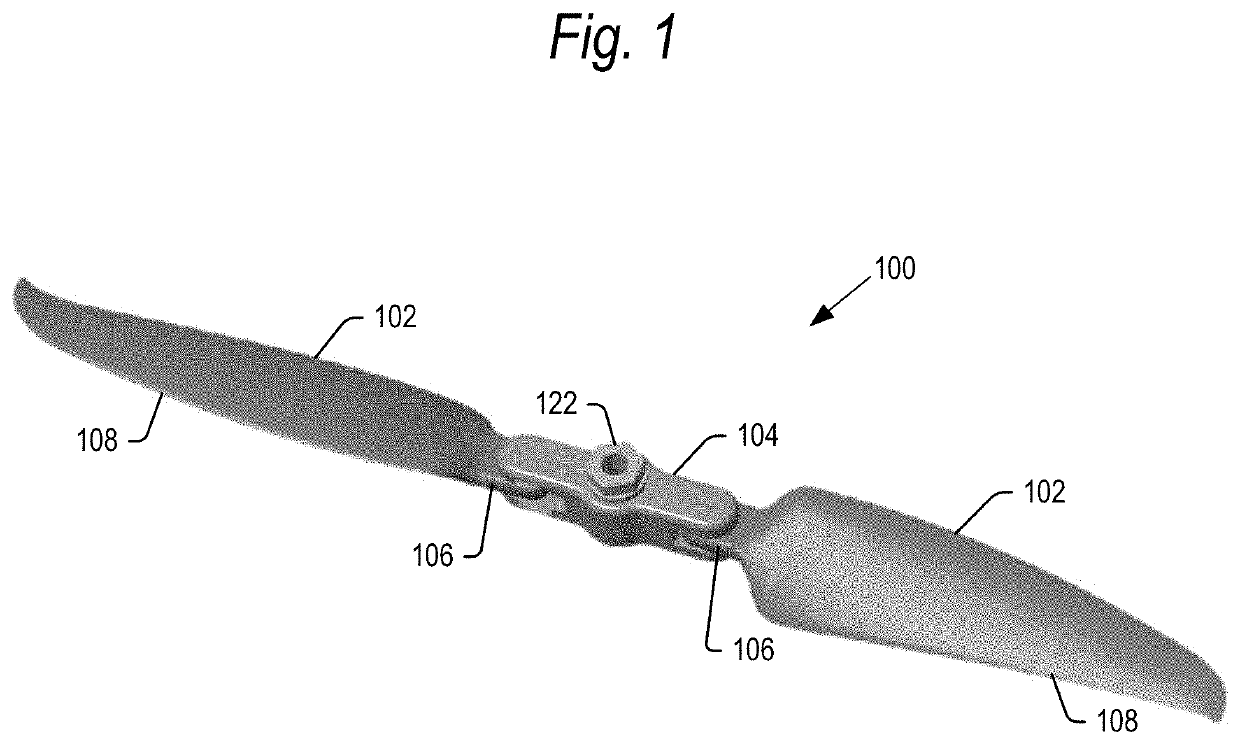
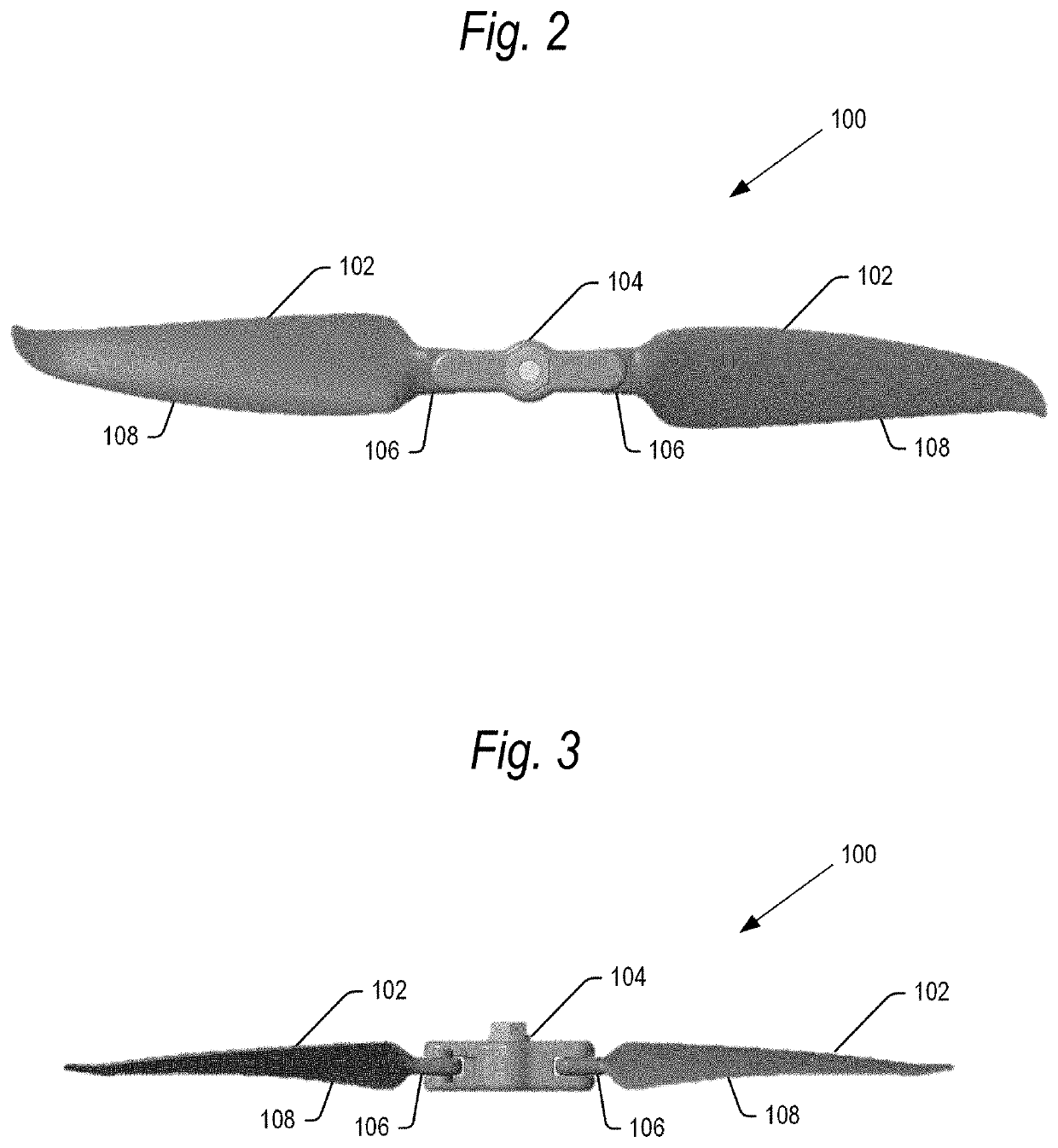
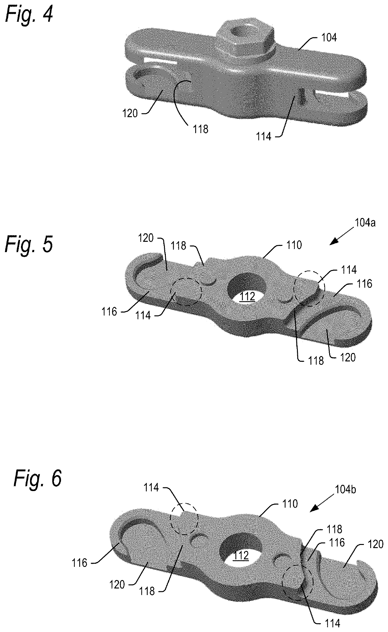
[0016]The present technology will now be described with reference to the figures, which in embodiments, relate to a quick release propeller for model airplanes including one or more blades mounted to a hub. For each blade, the hub includes a slot and a shoulder. Each blade includes a square base portion including pins which slide into the slot in the hub.

[0017]The slots are curved which prevents the blades from being removed unless they are rotated at an angle with respect to the hub. In particular, when the blade is oriented straight out from the hub (as would occur due to centrifugal forces on the blades during propeller rotation) the square base portion of the blade abuts against the shoulder to prevent the blade from being separated from the hub when the blade is oriented straight out from the hub. When the blade is rotating, centrifugal forces will also hold the blades in the slot to further prevent the blades from separating from the hub.

[0018]However, when propeller is not ro...


PUM


Abstract

A quick release propeller for model airplanes is disclosed including two or more blades mounted to a hub. For each blade, the hub includes a slot and a shoulder. Each blade includes a base portion having pins which slide into the slot in the hub. The slots are curved which prevents the blades from being removed unless they are rotated at predefined threshold angle with respect to the hub.

Description

FIELD[0001]The present invention relates to a propeller for a model aircraft, and in particular, to a propeller which may be quickly and easily removed when not rotating under power of the model aircraft engine.BACKGROUND[0002]Model aircraft including remotely controlled planes and helicopters include a propeller for providing thrust or lift and an engine for providing torque to the propeller. It may be desirable to remove and replace a propeller, such as for example where a propeller gets damaged during flight. However, given the need to ensure that the blades of a propeller remain secured and operational during flight, conventional propellers generally require tools for the removal, or at the very least complicated manual operations.DESCRIPTION OF THE DRAWINGS[0003]FIG. 1 is a perspective view of a propeller according to embodiments of the present technology.[0004]FIG. 2 is a top view of a propeller according to embodiments of the present technology.[0005]FIG. 3 is an edge view of...

Claims


Application Information

Patent Timeline
Patent Type & Authority Applications(United States)
IPC IPC(8): B64C11/28A63H27/00B64C11/04
CPCA63H27/02B64C11/04B64C2203/00B64C11/28A63H27/12B64U50/13B64C27/48B64U30/20B64U50/19
Inventor HOLIK, ROBERT
Owner LANDING PROD INC
Why Eureka
Try Eureka