Particulate matter detection sensor and particulate matter detection apparatus

Inactive Publication Date: 2020-01-16
DENSO CORP
View PDF0 Cites 0 Cited by
  • Summary
  • Abstract
  • Description
  • Claims
  • Application Information

AI Technical Summary

Benefits of technology

The patent text describes a particulate matter detection sensor and an apparatus for measuring the amount of particulate matter deposited on a surface. The sensor includes a detection conductive section and a pair of detection electrodes facing each other across the deposition surface. The detection conductive section is made of a conductive material with higher electrical resistivity than particulate matter, allowing an electric current to flow even when no particulate matter is deposited. When particulate matter is deposited, the electrical resistance between the detection electrodes changes, resulting in an electric current change. The sensor also includes a resistance monitor section to compensate for changes in the electrical resistance of the detection conductive section due to temperature. The apparatus includes a control section to measure the electrical resistance of the detection conductive section and calculate the deposition amount of particulate matter. The technical effect of this patent text is to provide a reliable and accurate method for measuring the amount of particulate matter deposited on a surface, which is useful in various fields such as environmental monitoring and manufacturing processes.

Problems solved by technology

The above PM sensor has a problem in which a detection value of the deposition amount of PM is highly variable according to the temperature.
This makes it difficult to accurately detect the deposition amount of PM.

Method used


Image

  • Particulate matter detection sensor and particulate matter detection apparatus
  • Particulate matter detection sensor and particulate matter detection apparatus
  • Particulate matter detection sensor and particulate matter detection apparatus

Examples


first embodiment

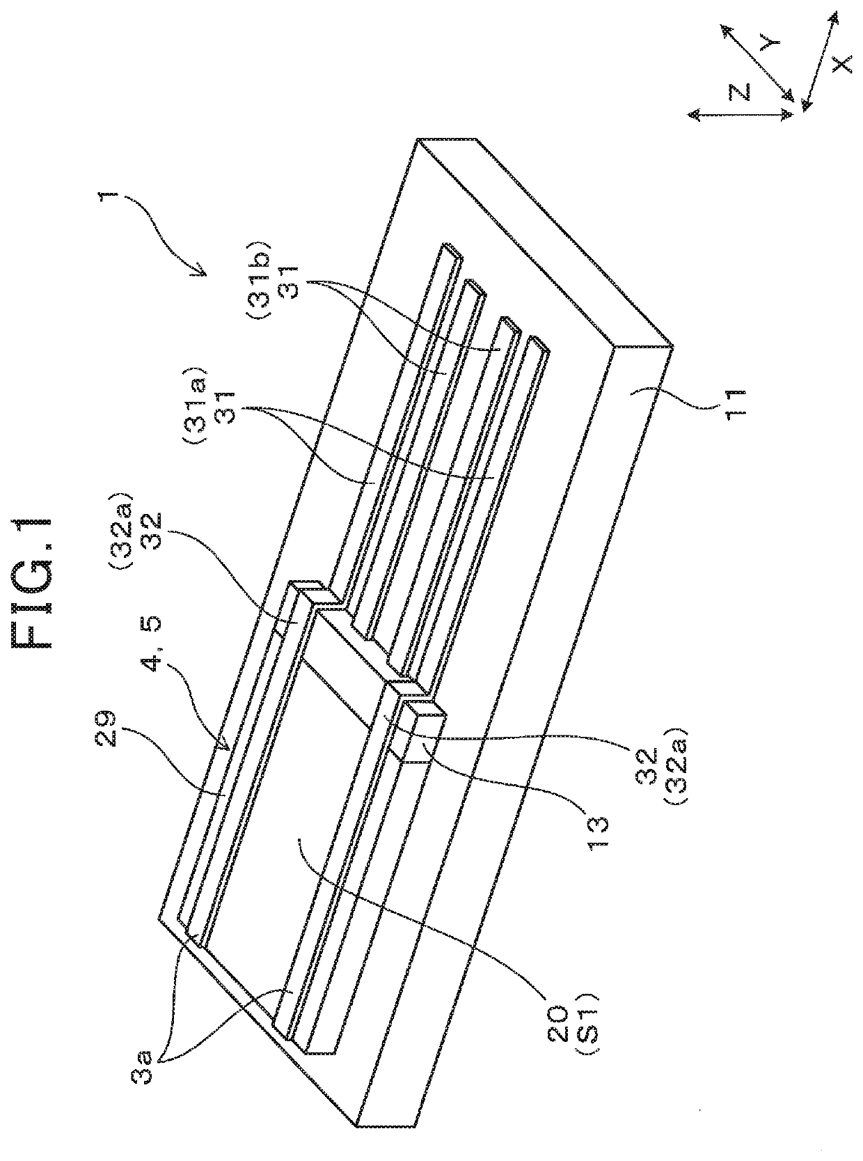
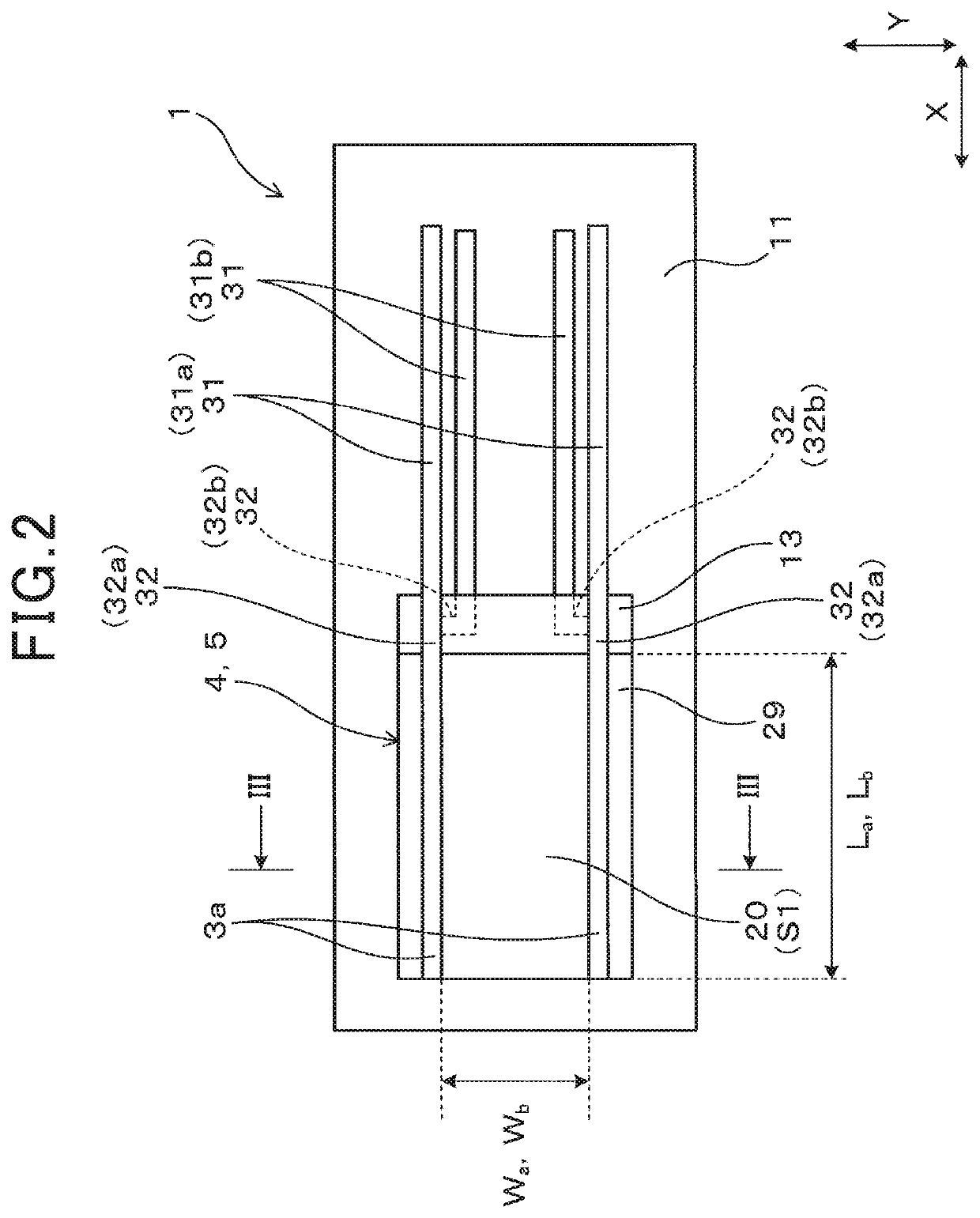
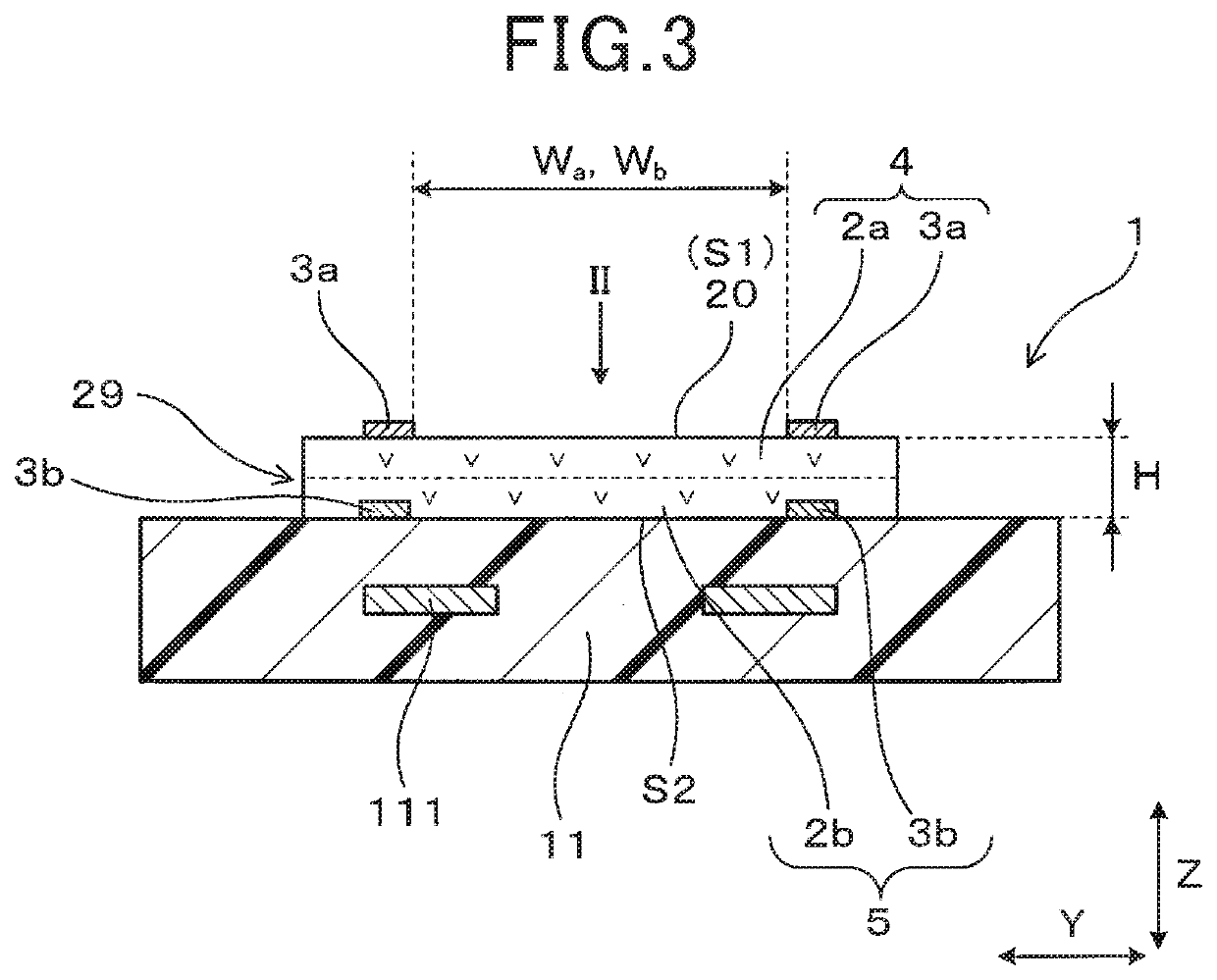
[0089]An embodiment of the particulate matter detection sensor and the particulate matter detection apparatus will be described with reference to FIGS. 1 to 12. The particulate matter detection sensor (i.e., PM sensor 1) of the present embodiment is used for detecting an amount of particulate matter 8 contained in exhaust gas. As illustrated in FIGS. 1 to 3, the PM sensor 1 includes a particulate matter detection section 4 and a resistance monitor section 5.

[0090]As illustrated in FIG. 3, the particulate matter detection section 4 includes a detection conductive section 2a and a pair of detection electrodes 3a. The detection conductive section 2a is made of a conductive material having a higher electrical resistivity than the PM 8.

[0091]The electrical resistivity of the PM 8 can be measured by a powder resistance measurement method below. Specifically, powder (PM) is placed in a predetermined cylindrical container (cross-sectional area: A) whose bottom and upper surfaces are electro...

second embodiment

[0133]The present embodiment is an example in which the configuration of the control section 6 is modified. As illustrated in FIG. 13, as with the first embodiment, the control section 6 of the present embodiment includes the main measurement section 61, the compensation measurement section 62, and the deposition amount calculation section 63. In addition, the control section 6 further includes a temperature calculation section 64.

[0134]The temperature calculation section 64 calculates the temperature of the detection conductive section 2a by using a measured value of the compensation resistance Rb. As shown in FIG. 14, the compensation resistance Rb has a certain relationship with the temperature. The control section 6 stores the relationship. The relationship is used to calculate a temperature Tx from a measured value of the compensation resistance Rb. For example, the calculated value of the temperature Tx can be used to determine whether when the heater 111 has generated heat, t...

third embodiment

[0138]The present embodiment is an example in which the configuration of the control section 6 is modified. As illustrated in FIG. 16, as with the second embodiment, the control section 6 of the present embodiment includes the main measurement section 61, the compensation measurement section 62, the deposition amount calculation section 63, and the temperature calculation section 64. In addition, the control section 6 further includes a deposition amount correction section 65. The deposition amount correction section 65 corrects a change in resistivity of the PM 8 according to the temperature by using a value of the temperature Tx calculated by the temperature calculation section 64. Thus, the deposition amount correction section 65 corrects the deposition amount of PM 8 calculated by the deposition amount calculation section 63.

[0139]For example, the correction of the deposition amount can be performed as below. As shown in FIG. 17, the resistivity of the PM 8 has a certain relatio...


PUM


Abstract

A detection conductive section and a monitor conductive section made of a conductive material having a higher electrical resistivity than that of PM are included. A deposition surface on which the PM is deposited is provided to the detection conductive section. A pair of detection electrodes are provided to the deposition surface. A pair of monitor electrodes are provided to the monitor conductive section. The configuration is made such that no PM is deposited on the monitor conductive section between the pair of monitor electrodes.

Description

CROSS-REFERENCE TO RELATED APPLICATIONS[0001]The present application is based on Japanese Patent Application No. 2016-201070 filed on Oct. 12, 2016, Japanese Patent Application No. 2017-74706 filed on Apr. 4, 2017, Japanese Patent Application No. 2017-80740 filed on Apr. 14, 2017, and Japanese Patent Application No. 2017-179388 filed on Sep. 19, 2017, the contents of which are incorporated herein by reference.TECHNICAL FIELD[0002]The present disclosure relates to a particulate matter detection sensor and a particulate matter detection apparatus for detecting an amount of particulate matter contained in exhaust gas.BACKGROUND ART[0003]Known particulate matter detection sensors (also termed PM sensors hereinafter) for detecting an amount of particulate matter (also termed PM hereinafter) contained in exhaust gas include a PM sensor including an insulating substrate provided with a deposition surface on which PM is deposited and a pair of detection electrodes provided on the deposition...

Claims


Application Information

Patent Timeline
IPC IPC(8): G01N15/06G01N1/22F01N13/00G01N27/04
CPCG01N1/2252G01N15/0656G01N27/043F01N13/008F01N2560/20F01N2560/05G01N15/0606G01N2015/0046
Inventor KOIKE, KAZUHIKOYAMAMOTO, MASAHIROMORITSUGU, MICHIYASUTAKIZAWA, KENSUKE
Owner DENSO CORP
Why Eureka
Try Eureka