Eureka AIR delivers breakthrough ideas for toughest innovation challenges, trusted by R&D personnel around the world.

User terminal, method, and computer program

Inactive Publication Date: 2020-03-05
NTI
View PDF0 Cites 0 Cited by
  • Summary
  • Abstract
  • Description
  • Claims
  • Application Information

AI Technical Summary

Benefits of technology

This patent is about a user terminal that allows users to display money information without giving up the possibility of others stalking and stealing the information. The user terminal displays money information using a unique method that reduces the risk of the information being stolen. In one embodiment, instead of displaying the money information directly, the user terminal displays a unique image that includes the money specifying information. The display control means prevents all the money specifying information from being displayed on the display at the same time, which makes it harder for the information to be stolen. Overall, the user terminal reduces the risk of money information being stolen and makes it easier to securely display and use the information.

Problems solved by technology

Of course, in a case where the one-time password generated by the settlement device does not match the one-time password transmitted from the user via the settlement terminal, the settlement device does not allow the settlement.

Method used


Image

  • User terminal, method, and computer program
  • User terminal, method, and computer program
  • User terminal, method, and computer program

Examples


first embodiment

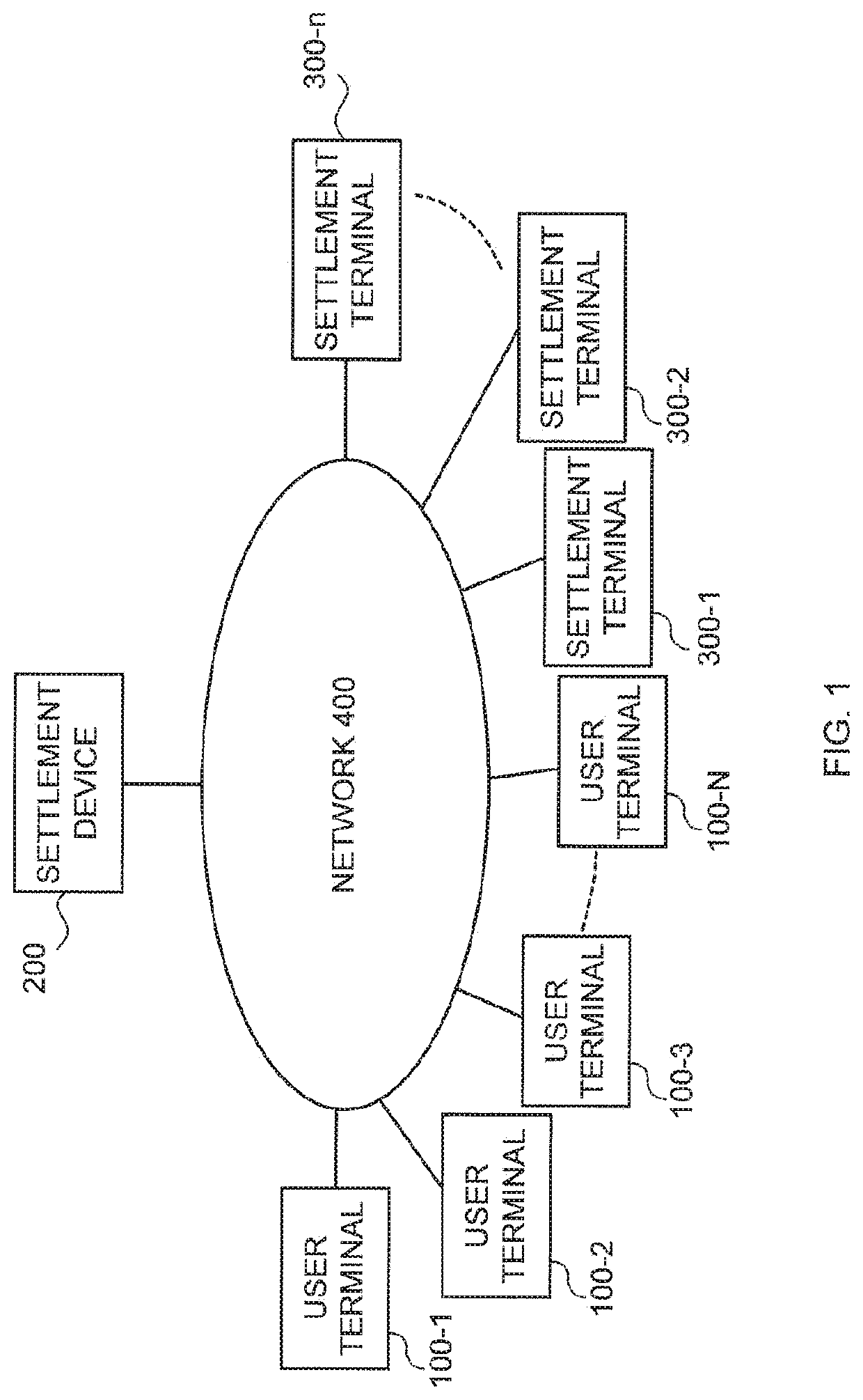
[0095]FIG. 1 schematically illustrates an overall configuration of a settlement system of a first embodiment.

[0096]The settlement system is configured to include a plurality of user terminals 100-1 to 100-N (hereinafter, also simply referred to as a “user terminal 100”), a settlement device 200 and settlement terminals 300-1 to 300-N (hereinafter, also simply referred to as a “settlement terminal 300”). All of these can be connected to a network 400.

[0097]The network 400 is the Internet in this embodiment, while the network is not limited to the Internet.

[0098]The user terminal 100 corresponds to the user terminal described in Background Art of the present invention, and includes a computer. In more details, the user terminal 100 in this embodiment is configured with a general-purpose computer. In this embodiment, while description will be provided assuming that each user has one user terminal 100, one user may possess a plurality of user terminals 100. If this case is compared to a...

example 1

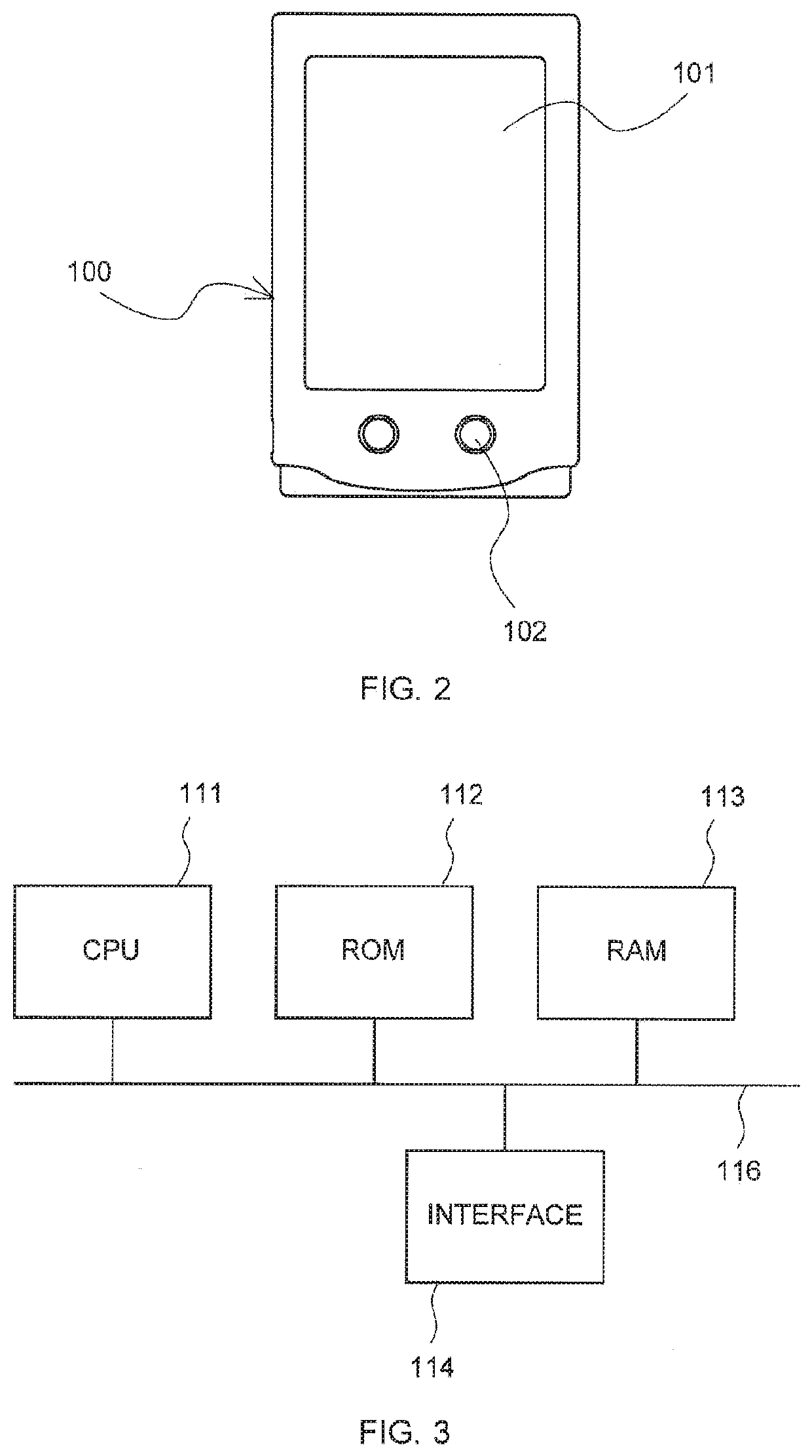
[0234]An image in this example is as illustrated in FIGS. 21(A0, 21(B), and 21(C). Reference numeral 101 in FIGS. 21(A), 21(B), and 21(C) denotes the display 101. Further, Reference character I1 denotes an image. Among the image I1, only a portion overlapping with the display 101 is displayed on the display 101. Note that, also in the following examples, Reference numeral 101 denotes the display 101, and reference characters in which numbers are added to I denotes images. Among each image, only a portion overlapping with the display 101 is displayed on the display 101 in a similar manner to Example 1.

[0235]The image I1 in Example 1 has the same width as that of the display 101 as illustrated in FIGS. 21(A), 21(B), and 21(C), and is longer in a vertical direction than the display 101. The one-time password is displayed as is in the image I1. In this embodiment, it is assumed as an example that the one-time password of “01563894451” is generated. In the image I1, the one-time password...

example 2

[0240]An image 12 in this example is as illustrated in FIG. 22. The image 12 in this example has the same size as that of the display 101. Therefore, the image 12 is not scrolled with respect to the display 101.

[0241]Further, a cylindrical-shaped cylindrical member I2A is displayed in the image 12. The one-time password is attached on an outer surface of the cylindrical member I2A so as to surround the circumference. A dot on 0 in the drawing indicates a starting point of the one-time password.

[0242]The cylindrical member I2A in this example can rotate around the axis in the image 12, and the user can freely rotate the cylindrical member I2A in the image 12 by manipulating the input device 102. By causing the cylindrical member I2A to make one turn, the whole of the one-time password displayed on a side surface of the cylindrical member I2A can be displayed on the display 101. Meanwhile, if the user does not rotate the cylindrical member I2A, because the one-time password displayed ...


PUM


Abstract

A technique of securely handing over money information which is information having monetary value, recorded within a portable user terminal, to a person who is to receive payment from a person who makes payment is proposed. A one-time password as money information to be displayed on a display 101 of the user terminal is displayed fully in a length in a vertical direction of an image I1 which has a larger length in the vertical direction than that of the display 101. The image I1 can be scrolled in the vertical direction with respect to the display 101, so that the whole of the one-time password can be browsed. Meanwhile, there is no moment at which the whole of the one-time password is displayed on the display 101 at the same time.

Description

TECHNICAL FIELD[0001]The present invention relates to a technique for allowing a person who makes payment to securely present money information which is information having monetary value to a person who is to receive the payment in a new settlement system which is a substitute for a credit card.BACKGROUND ART[0002]The present inventor proposes a new settlement system which is a substitute for a credit card. This is a settlement system including user terminals, settlement terminals, and a settlement device which can perform communication with the user terminals and the settlement terminals via the Internet and other networks.[0003]Applications of the settlement system are filed as Japanese patent applications, for example, as Japanese Patent Application No. 2015-243564, Japanese Patent Application No. 2015-250700, Japanese Patent Application No. 2015-256028, or the like.[0004]Outline of these settlement systems will be simply described. The user terminal, which is possessed by a user...

Claims


Application Information

Patent Timeline
IPC IPC(8): G06Q20/36G06Q20/38G06Q20/32G06Q20/40G06F3/14G06F3/0485
CPCG06Q20/3274G06Q2220/00G06F3/0485G06F3/14G06Q20/363G06Q20/40145G06Q20/385H04M1/00G06F21/60G06Q20/30H04L9/50
Inventor NAKAMURA, TAKATOSHI
Owner NTI
Why Eureka
Eureka Blog
Learn More