
Fingerprint sensor and method of transmitting a sensor image to reduce data size and data rate

Inactive Publication Date: 2011-03-29
SMSC HLDG
View PDF13 Cites 17 Cited by
  • Summary
  • Abstract
  • Description
  • Claims
  • Application Information

AI Technical Summary

Benefits of technology

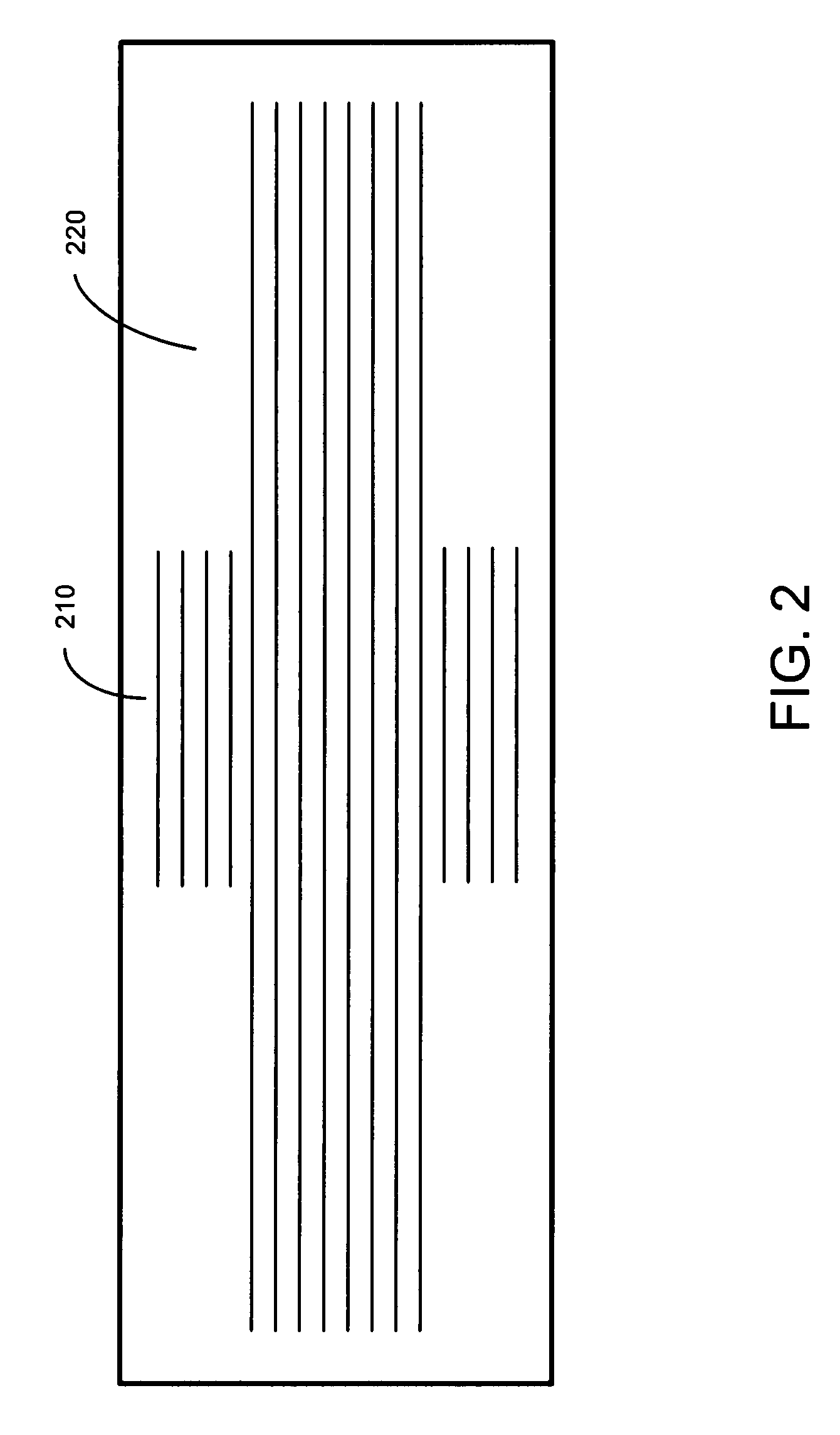
[0017]A series of non-rectangular two-dimensional images is transmitted from a fingerprint sensor to a host for processing and combining into a full fingerprint image. The images have several active lines that are the full width of the sensor. The images have a central region with additional narrow horizontal lines used for alignment that are a fraction of the full width to provide image information used

Problems solved by technology

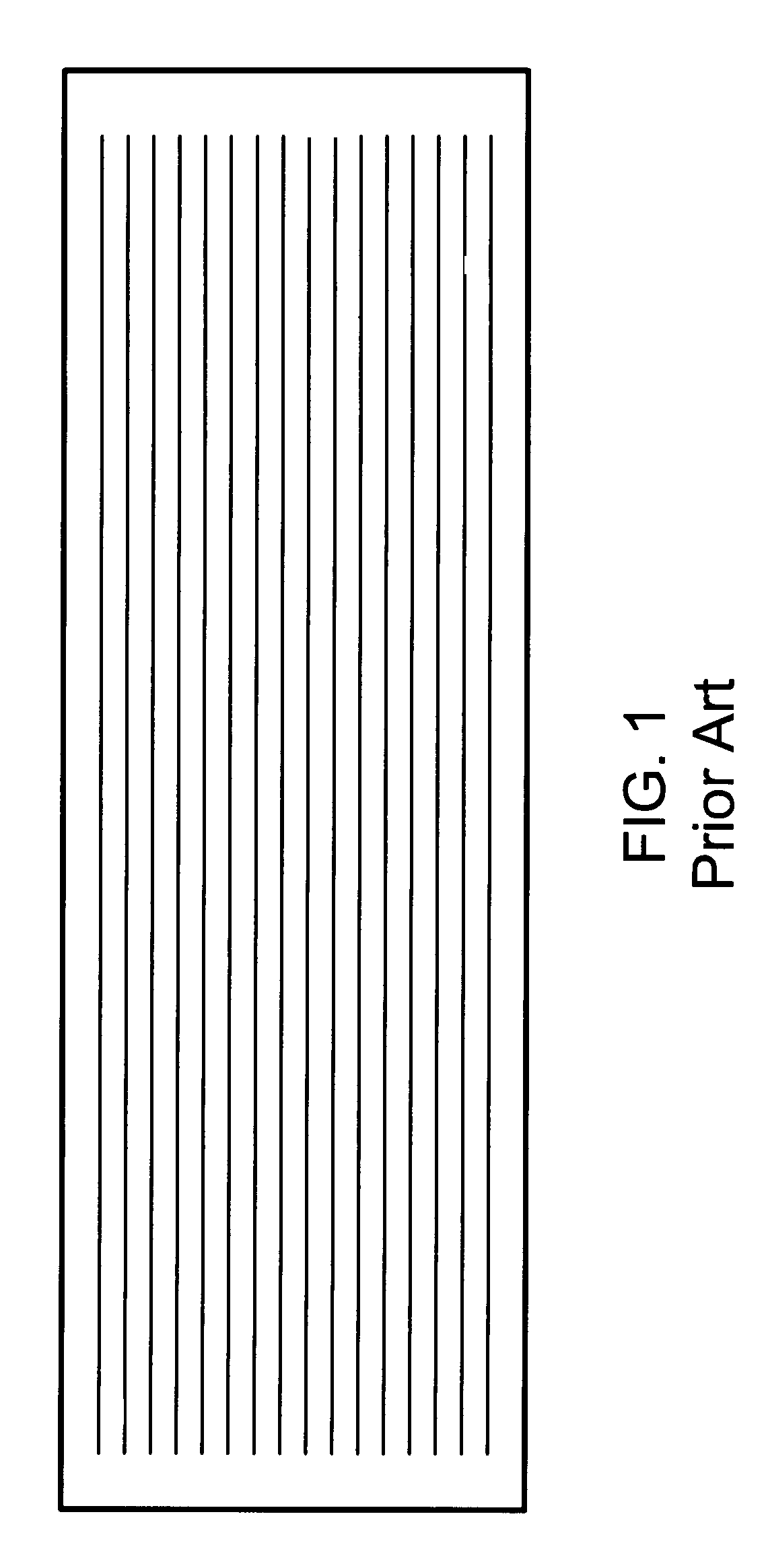
A specialized interface for the sensor precludes compatibility with existing devices that are not designed with a physical layer interface suitable for connection to the sensor.
A USB interface in a fingerprint sensor requires significant die area on the device and thereby increases cost of the sensor.
Each input or output (I / O) pin requires a bond wire pad on the integrated circuit, which uses die area and thus increases cost.
If the bandwidth of the interface is not sufficient, image data may be lost.
The bandwidth of the analog interface is generally limited due to its typical use sensing low bandwidth signals.
The bandwidth required for conventional sensors may exceed the capability of a typical analog or digital interface.
Too few lines of overlap decrease the quality of the reconstructed image.
The prior art does not teach a solution to the objective of limiting the bandwidth of the image data to match available interfaces.

Method used


Image

  • Fingerprint sensor and method of transmitting a sensor image to reduce data size and data rate
  • Fingerprint sensor and method of transmitting a sensor image to reduce data size and data rate
  • Fingerprint sensor and method of transmitting a sensor image to reduce data size and data rate

Examples


Embodiment Construction

[0022]FIG. 2 shows a configuration of the transmitted portion of a fingerprint sensor array according to the present invention. The long axis of the sensor is identified as horizontal and the short axis is identified as vertical, although the actual orientation of the sensor is not critical to the operation. A line of pixels along the long axis is a horizontal line or row. The readout order of the pixels can be by columns or rows.

[0023]According to the present invention, the central region 210 of the frames is used to perform the correlation without using the full width of the sensor. The pixel values in the corner regions 220 are not transmitted. Accuracy of determining the displacement of overlapping frames is improved by having more horizontal lines of information to correlate between successive frames, which increases the effective vertical overlap of the frames. The tall and narrow-width central region provides sufficient information by utilizing additional narrow horizontal li...


PUM


Abstract

A fingerprint imager uses a non-rectangular image readout to reduce the bandwidth and data size of the read-out image. Narrow-width rows in the central portion of the image are used to align successive partial image frames of the fingerprint to reconstruct a full image of the fingerprint using full-width rows of the fingerprint frames.

Description

RELATED APPLICATIONS[0001]This application claims priority from U.S. provisional application No. 60 / 824,708 filed Sep. 6, 2006 entitled “Fingerprint sensor and method of transmitting a sensor image to reduce data size and data rate”, incorporated herein by reference.BACKGROUND[0002]1. Field of Invention[0003]The invention relates to fingerprint imaging and specifically to a readout sequence and array shape that minimizes the data needed to reconstruct an image.[0004]2. Prior Art[0005]Fingerprint scanners are one form of biometric verification used to access data and devices. Devices that have potential use for biometric verification include laptop computers, personal digital assistants, cellular or mobile telephone handsets, and any other device requiring access restriction or security.[0006]Fingerprint sensing technology is well known. One method uses an alternating current excitation signal that propagates an electric field through the finger while a capacitive sensor detects the ...

Claims


Application Information

Patent Timeline
IPC IPC(8): G06K9/28G06V30/144
CPCG06K9/00026G06V40/1335
Inventor THOMAS, CHRISTOPHER
Owner SMSC HLDG
Learn More