Method for partitioning a predetermined placement of parts intended to be cut in a flexible sheet material

a flexible sheet material and predetermined technology, applied in forecasting, clothes making applications, data processing applications, etc., can solve the problems of reducing the overall cost of production of such parts, and reducing the efficiency of layout, so as to avoid cutting defects in sensitive areas. , the effect of reducing the layout efficiency

Active Publication Date: 2020-03-12
LECTRA SA (FR)
View PDF0 Cites 6 Cited by
  • Summary
  • Abstract
  • Description
  • Claims
  • Application Information

AI Technical Summary

Benefits of technology

[0009]A main object of the present invention is thus to mitigate such drawbacks by proposing to partition a predetermined layout of parts so as to avoid cutting defects in sensitive zones, but without that reducing the efficiency of the layout.

Problems solved by technology

Specifically, those layouts are cut up in highly irregular manner and any variation in the optimization of the layout implies non-negligible effects on the consumption of material, and thus on the overall cost of producing such parts.
In practice, recurrent problems appear while cutting up layouts, in particular in boundary zones between two sets of parts of the layout that are cut in succession by the same cutter tool.
Specifically, it can happen that when the cutter tool begins to cut out a part, parts in neighboring sets of parts have already been cut out.
Unfortunately, in this situation, the effect of suction applied to the material, which normally serves to hold the material against the working table during cutting, is greatly reduced around the part for cutting out because of the close proximity of the part for cutting out with parts that have already been cut out.
Consequently, the part for cutting out is no longer held so effectively against the working table, such that the cutter tool tends to take material with it as it moves.
Usually, this gives rise to cutting defects on those parts.
In order to remedy that problem, the solution consisting in adding spacings between each of the parts in the optimized layout (i.e. providing a margin around each part) is not entirely satisfactory.
In contrast, adding such spacings leads to a loss of material that can be significant in that type of layout where the number of parts is high (the greater the number of parts, the amount of space that is lost by adding margins is proportionally greater).
However, as mentioned above, optimizing losses while conserving a high speed of cutting is a critical issue for manufacturers who make use of layouts of this type.

Method used


Image

  • Method for partitioning a predetermined placement of parts intended to be cut in a flexible sheet material
  • Method for partitioning a predetermined placement of parts intended to be cut in a flexible sheet material
  • Method for partitioning a predetermined placement of parts intended to be cut in a flexible sheet material

Examples


Embodiment Construction

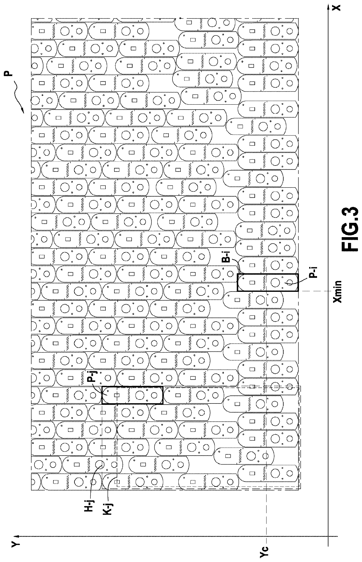
[0034]The invention applies to laying out parts that are to be cut out from a flexible sheet material by digitally controlled cutter machines including a working table on which the parts are cut out.

[0035]In known manner, the working table of such a cutter machine is constituted by the top surface of an endless conveyor received in a box within which suction can be established using a technique well known to the person skilled in the art. A flexible sheet material is placed on the endless conveyor, which supports and moves the material continuously along the working table. The material is caused to advance on the working table in a longitudinal direction X under the control of the drive motor of the conveyor.

[0036]The installation also includes a cutter system made up of one or more cutter tools that can move horizontally along the longitudinal direction X of the conveyor and also along a transverse direction Y perpendicular to the direction X. Each of these cutter tools moves over ...


PUM


Abstract

A method of partitioning involves a predetermined layout of parts that are to be cut out from a sheet of flexible material by moving at least one cutter tool along two directions in at least two distinct and determined cutting windows along which the material is advanced in succession. Starting from a predetermined layout of the parts in the material, the method comprises: automatically creating mutually distinct groups of parts by allocating each part to a single group of parts as a function of its geometrical position, each group of parts being associated, for cutting out, with a single cutter tool and with a single cutting window; and applying spacings between the various groups of parts.

Description

BACKGROUND OF THE INVENTION[0001]The present invention relates to a method of partitioning a predetermined layout of parts that are to be cut out from a flexible sheet material.[0002]The field of application of the invention is in particular the field of cutter machines that comprise a work table on which parts are cut out by moving one or more cutter tools relative to the material in two directions, successive portions of the material being brought into the working zone of the cutter tools.[0003]This applies in particular to digitally-controlled cutter machines that are used for cutting out fabrics, felts, leathers, or other flexible sheet materials in the clothing, furnishing, automobile, etc. industries.[0004]With such cutter machines, the parts are cut out using a predetermined layout that is defined in such a manner as to minimize losses of material. In order to limit the overall size of such cutter machines, the cutting window (or work zone) in which each cutter tool operates ...

Claims


Application Information

Patent Timeline
Patent Type & Authority Applications(United States)
IPC IPC(8): B26D5/00G06Q10/04B26F1/38B26D7/01B26D7/18
CPCB26D7/018G06Q10/043B26F1/3806B26D7/18B26D5/005A41H3/007
Inventor VALEZE, BRUNOBOURGET, YOHAN MICHAEL CHRISTOPHE
Owner LECTRA SA (FR)
Why Eureka
Try Eureka