

Slide fastener
- Summary
- Abstract
- Description
- Claims
- Application Information
AI Technical Summary
Benefits of technology
Problems solved by technology
Method used
Image

Examples
Embodiment Construction
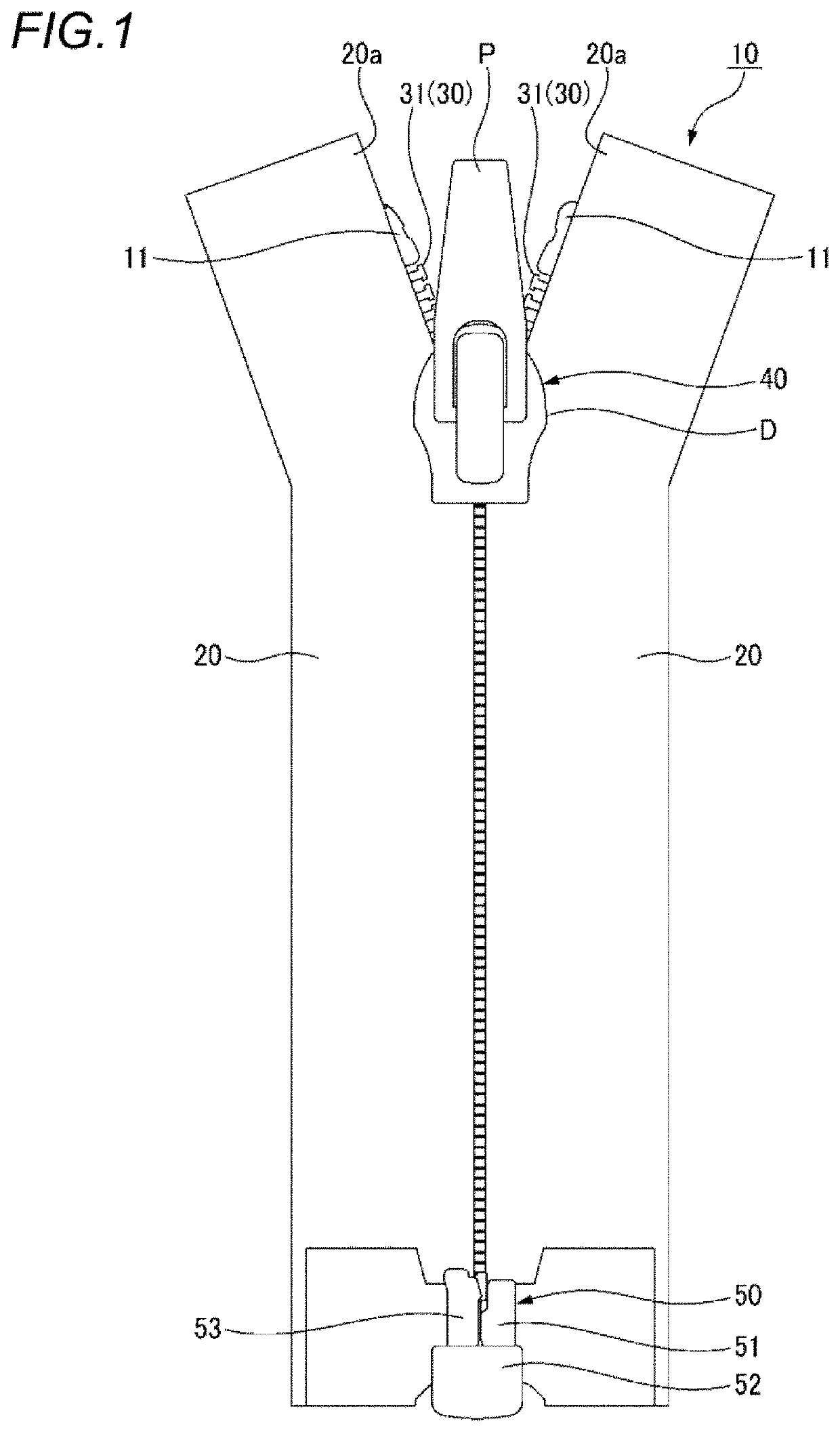
[0029]Hereinafter, one embodiment of a slide fastener according to the present invention will be described in detail with reference to the accompanying drawings. In the following description, an upper side refers to a near side with respect to the paper surface of FIG. 1; a lower side refers to a far side with respect to the paper surface of FIG. 1; a front side refers to an upper side with respect to the paper surface of FIG. 1; a rear side refers to a lower side with respect to the paper surface of FIG. 1; a left side refers to a left side with respect to the paper surface of FIG. 1; and a right side refers to a right side with respect to the paper surface of FIG. 1. A right and left direction is also referred to as a widthwise direction. In addition, a front and rear direction is also referred to as a lengthwise direction.
[0030]As shown in FIG. 1, a slide fastener 10 of the present embodiment includes a pair of right and left woven knitted fastener tapes 20; a pair of right and l...
PUM
 Abstract
Description
Claims
Application Information