Structure of removable electrical connector

Inactive Publication Date: 2006-07-25
YAZAKI CORP
View PDF10 Cites 2 Cited by
  • Summary
  • Abstract
  • Description
  • Claims
  • Application Information

AI Technical Summary

Benefits of technology

[0029]According to above, by rotating the connector housing around the pivoting part, the engaging portion is engaged from and disengaged with the receiving part to allow the connector housing to be removable. Therefore, by pressing a position distant from the pivoting part on the connector housing, according to the principle of leverage, the force given to the connector housing to attach and remove the removable electrical connector can be reduced. Namely, the removable electrical connector can be attached and removed by the force less than the force in a longitudinal direction of the metal terminal received by the connector housing.
[0040]According to the present invention, when the connector housing is arranged at the pivoting part, the pivot projection projecting outward from the first edge of the connector housing is movable in the concave in an insertion direction of the connector housing. Therefore, when the connector housing is rotated around the pivoting part, the pivot projection and the concave can be prevented from blocking each other.
[0041]Further, the inclined surface is inclined outward, and arranged adjacent to an edge corresponding to the first edge of the connector housing, at an inner side of the receiving part. Therefore, when the connector housing is rotated around the pivoting part, the inner side surface as the inclined surface of the receiving part and the outer side surface of the connector housing can be prevented from blocking each other.
[0042]Therefore, the connector housing can be reliably rotated around the pivoting part, so that the connector can be attached to and removed from the receiving part reliably.
[0051]According to the present invention, because the structure of the present invention satisfies the formula (5), the pivot projection can be reliably inserted into the concave. Namely, the connector can be attached reliably to the receiving part. Further, because this structure of the present invention satisfies the formula (6), the connector can be reliably removed from the receiving part.
[0052]According to the present invention, because the structure of the present invention satisfies the formula (7), the connector can be reliably removed from the receiving part.

Problems solved by technology

However, in the structure of a removable electrical connector described above, when removing from the mating connector, the one connector housing is deformed by hitting the projection.
Therefore, force for attaching and removing the connectors, which is given to the connectors, tends to be large.
Therefore, it is difficult to removably attach the connectors together, so that a workability of engaging and disengaging the connectors tends to be decreased.
However, the projection of the mating connector may be damaged by the tool.

Method used


Image

  • Structure of removable electrical connector
  • Structure of removable electrical connector
  • Structure of removable electrical connector

Examples


Embodiment Construction

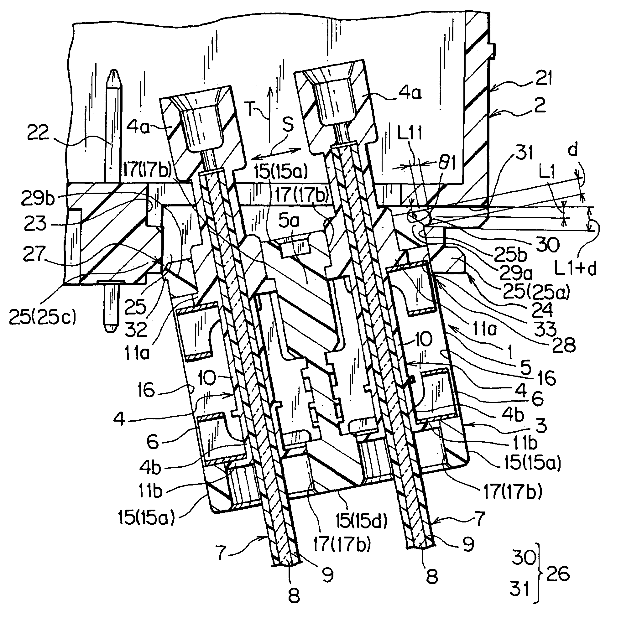
[0065]One embodiment of a structure 1 of a removable electrical connector according to the present invention will be described with reference to the attached drawings. The structure 1 of this embodiment allows an optical connector 3 for use in electrical equipment 2 of a vehicle to be removable.

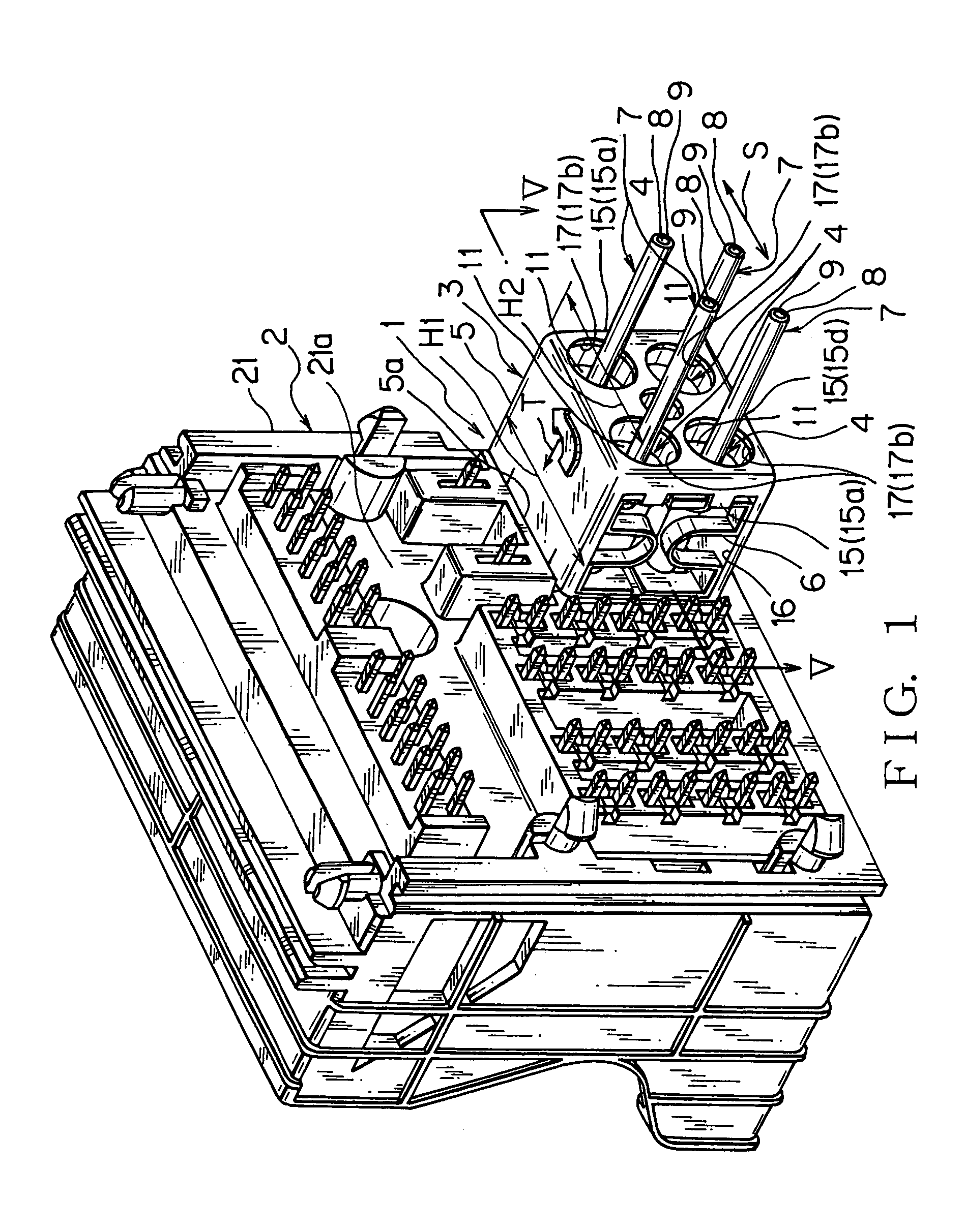
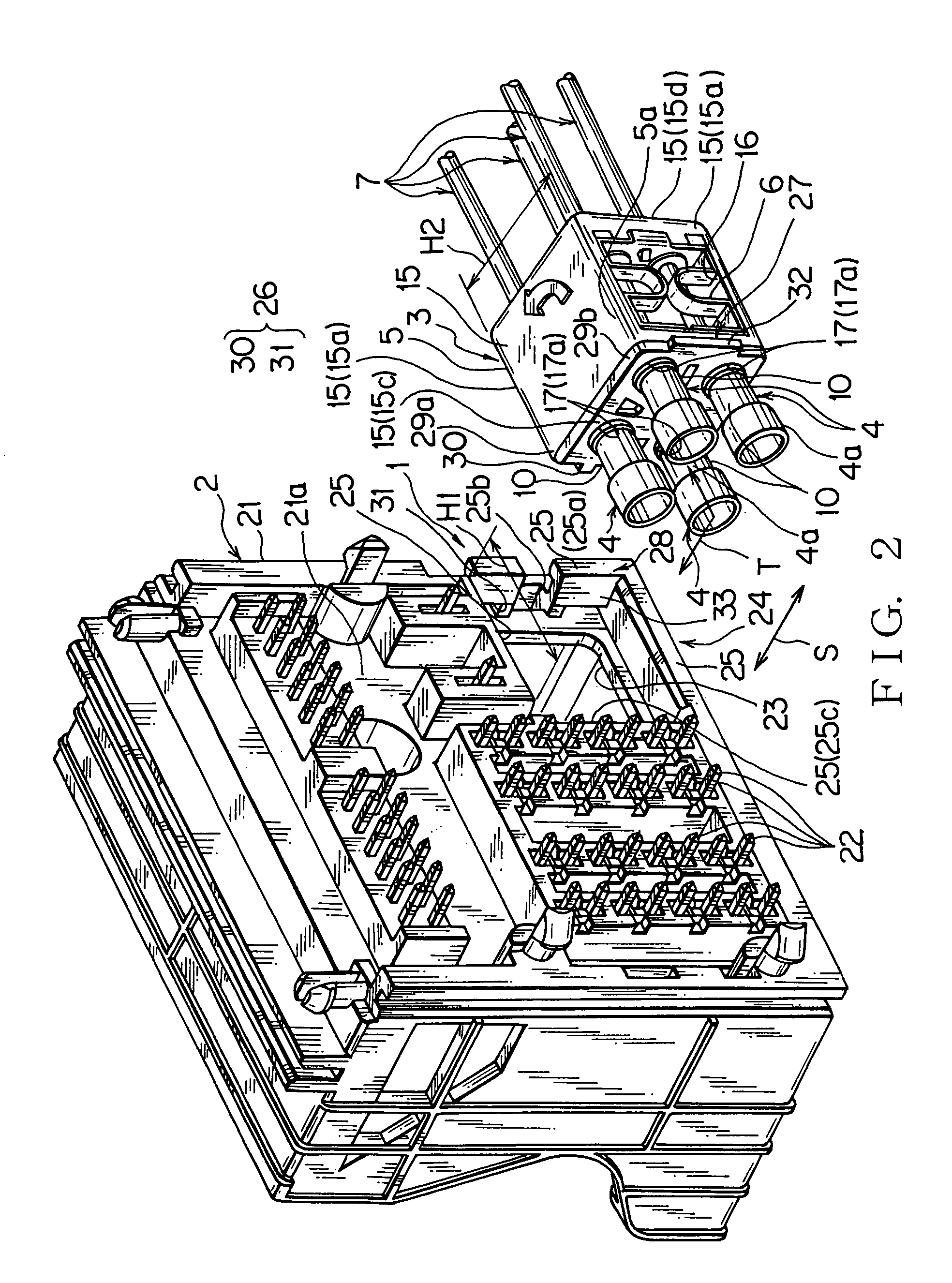
[0066]As shown in FIGS. 1 and 2, the electrical equipment 2 has a body 21 made of synthetic resin, a plurality of terminals 22 embedded in the body 21, a through hole 23, and a receiving part 24 for receiving a mating connector (hereinafter referred to as “receiving part”). The body 21 has a box-like shape. One end of each terminal 22 projects outside of the body 21, the other end projects inside the body, and a middle of each terminal 22 is embedded in the body 21. The one end of each terminal 22 is connected to a mating terminal of various connectors (not shown).

[0067]The through hole 23 penetrates an outer wall 21a of the body 21, as shown in FIG. 1. The through hole 23 has a rectangular s...


PUM


Abstract

For providing a removable electrical connector to be attached and removed easily without being damaged, a structure of the removable electrical connector has a receiving part, a pivoting part, an engaging and disengaging part, and a rotation allowing part. The removable electrical connector is pivoted around a first edge of the connector housing of the pivoting part. A second edge opposed to the first edge of the removable electrical connector of the engaging and disengaging part is engaged with and disengaged from the receiving part of a mating connector or a mating equipment. The rotation allowing part allows the removable electrical connector to rotate around the pivoting part.

Description

FIELD OF THE INVENTION[0001]The present invention is related to a structure of a removable connector for allowing an optical connector to be attached to and removed from electronic equipment easily, where the optical connector receives terminals of optical fibers, and the optical fibers transmit optical signals.DESCRIPTION OF THE RELATED ART[0002]Various types of electronic equipment are mounted on a vehicle. In a vehicle, a wire harness is arranged for transmitting specific electric power and signals to the electronic equipment. The wire harness has a plurality of wires and connectors for transmitting signals. An electric wire, having a conductive core and a sheath for covering the core, and an optical cable, having an optical fiber and a clad for covering the fiber, are used as the wires. The connector has a metal terminal (for example, a ferrule) and a connector housing for receiving the metal terminal.[0003]Some of the connectors of the wire harness arranged in a vehicle are con...

Claims


Application Information

Patent Timeline
IPC IPC(8): H01R13/73H01R13/627H01R13/631
CPCH01R13/6271H01R13/6315
Inventor YAMAGUCHI, NOBORUOZAKI, MASAHITO
Owner YAZAKI CORP
Why Eureka
Try Eureka