
Device and method for optically sorting bulk material

a technology of optical sorting and bulk materials, applied in the direction of measurement devices, material analysis by optical means, instruments, etc., can solve the problems of reducing material throughput and thus economic utility at a given system performance, implementing a homogeneous background, and unable to reliably recognize color, etc., to achieve the highest selection quality and increase performance

Inactive Publication Date: 2012-10-09
FRAUNHOFER GESELLSCHAFT ZUR FOERDERUNG DER ANGEWANDTEN FORSCHUNG EV
View PDF12 Cites 2 Cited by
  • Summary
  • Abstract
  • Description
  • Claims
  • Application Information

AI Technical Summary

Benefits of technology

[0017]The invention is a refined device and method for the optical selection of components of at least one fraction of a bulk material stream conveyed along a conveyance direction. The invention includes a camera unit, whose viewing direction is oriented on the bulk material stream, a background, situated behind the bulk material stream in the camera viewing direction, whose color is adaptable to the color of a selected fraction of components of the bulk material stream, an analysis and control unit, connected to the camera unit, in which control commands for a separation unit, which is capable of separating the components to be selected out of the bulk material stream upon activation, are generated according to a decision criterion. An increase of the performance is possible regarding sorting quality and throughput, in particular during the sorting of small objects. Furthermore, it is to be possible to adapt the color of the background, in front of which the bulk material stream is optically registered by the camera, as much as possible without great effort, preferably automatically, to the particular sorting task. The device is also usable from economic aspects in those cases in which the sorting task changes frequently and in rapid succession. Furthermore, a corresponding method allows automatic adaptation of the particle selection to different sorting tasks by the simplest possible method steps, and with the highest selection quality.
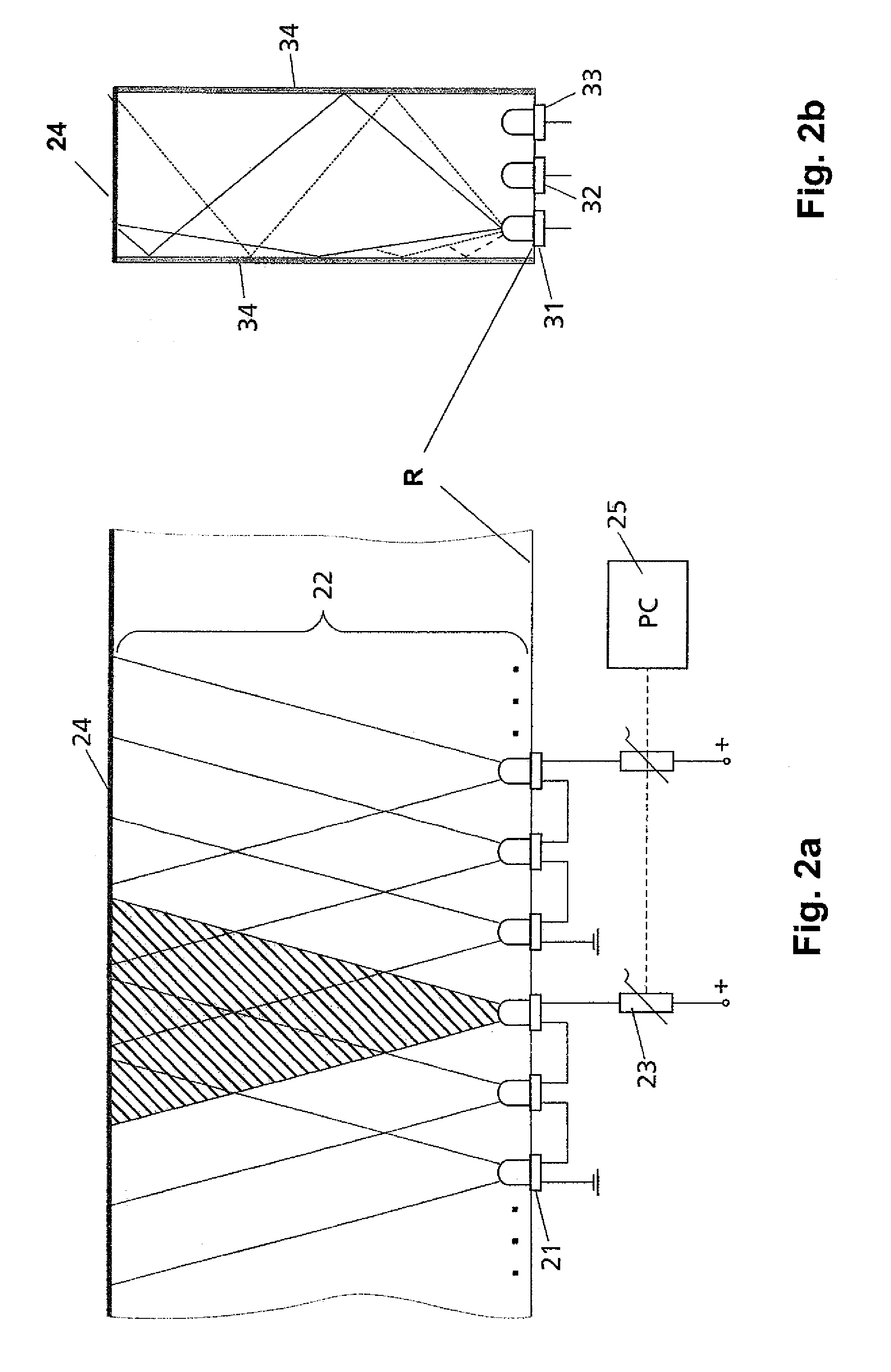
[0018]According to the invention, a device for the optical selection of components of at least one fraction from a bulk material stream, which is conveyed along a conveyance direction, is distinguished in that the camera unit is a location-resolving camera and has at least two and preferably three color channels. Each color has different spectral sensitivities. The background has a plurality of individual illuminants, of which each individual illuminant emits light having a spectral distribution which is adapted to one of the spectral sensitivity ranges of the camera in each case. Furthermore, the analysis and control unit has a unit which allows the determination of the local curve of a color value in the direction of the sorting width. The sorting width is defined as the direction transverse to the optical axis of the camera and transverse to the conveyance direction. Using this unit, the color value, which is ascertained by the camera, of the component which is not to be sorted out from the bulk material stream may be detected locally and resolved along the entire sorting width. This local curve of the color value is not necessarily constant over the entire sorting width, but rather, inter alia, subject to changes in particular at the boundary areas of the sorting width because of illumination. It is used as a basis for a regulating module, which sets the individual illuminants in regard to their brightness in such a way that the color of the background assumes the local curve of the specific color value. In this way, it may be ensured that the entire sorting width may be used in the same quality to register color differences between rejected parts and the good parts in the bulk material stream, by which the reliability in recognizing rejected parts may be improved.
[0025]In an especially preferred way, lamps in the form of LEDs, which have different colors, suggest themselves as the illuminants, the different colors each corresponding to one of the color channels of the camera. Alternatively, it is possible to implement the colors of the individual illuminants by a combination of a suitably selected light having a color filter specially adapted to the particular spectral sensitivity range of a color channel of the camera unit. Thus, color filters may also be used in combination with LEDs to minimize crosstalk if the particular emission spectrum of the LED is implemented so that the light of this LED may be detected by more than one color channel of the camera unit. Fundamentally, arbitrary illuminants which correspond to the above requirements may be used. LEDs whose emission spectra have been adapted beforehand to the spectral sensitivity range of one color channel of the camera in each case are especially advantageous.

Problems solved by technology

However, this procedure is only advisable if the objects to be recognized are sufficiently large in comparison to the local resolution of the imaging optics and a camera and correspondingly sufficiently many pixels are available for recognizing color and shape of the object.
In contrast, if the objects are too small, their color may no longer be reliably recognized.
However, the material throughput and thus the economic utility are thus decreased at a given system performance.
However, the difficulty results from implementing a homogeneous background in the desired color and brightness.
In all of the above cases, the setting of background lighting in the color of the material flow to be let through is very complex and is only worth it if the same product is sorted on the relevant sorting machine over a longer period of time.
Further disadvantages of the configurations used until now are the susceptibility of the background to contamination, fading of the color, or mismatching as a result of lamp aging.
Moreover, it is only possible to produce the desired brightness curve over the entire sorting width with quite high effort.

Method used


Image

  • Device and method for optically sorting bulk material
  • Device and method for optically sorting bulk material
  • Device and method for optically sorting bulk material

Examples


Embodiment Construction

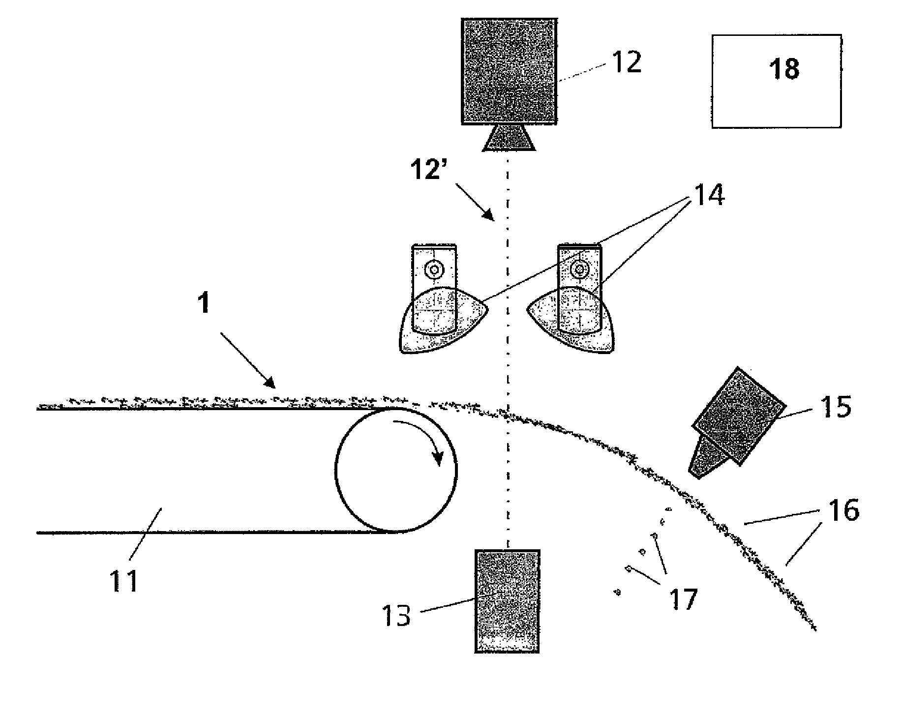
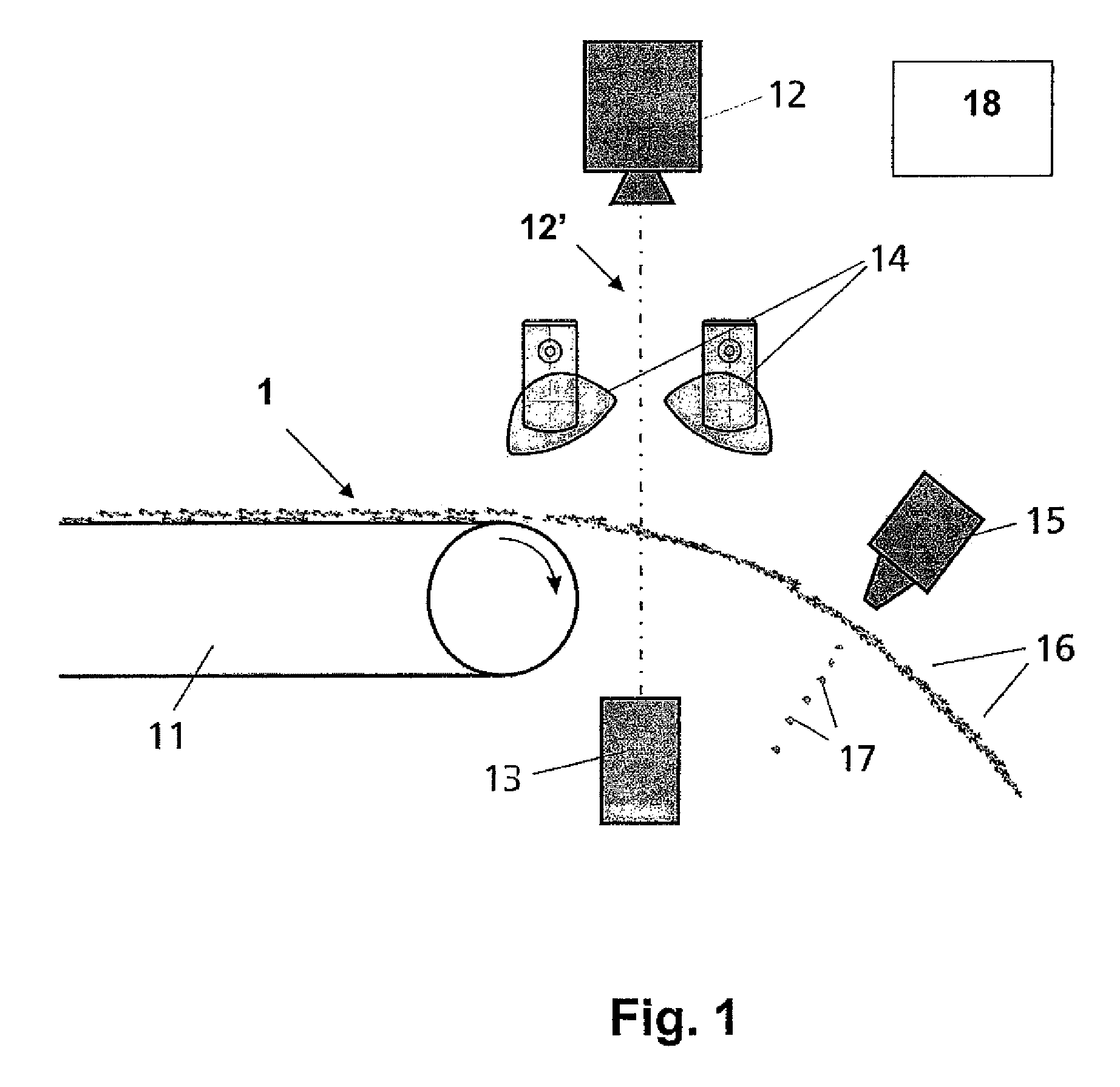
[0032]FIG. 1 shows the schematic construction of a device for the optical selection of components of at least one fraction, which is preferably distinguished by the color, from a bulk material stream 1 conveyed along a conveyance direction 11, which, after leaving the conveyance direction 11 along a free trajectory, is captured in a collection container (not shown in greater detail). A color-capable camera unit 12, whose viewing direction 12′ registers the bulk material stream 1 in front of a background 13, whose color is adaptively adaptable, is located largely perpendicular to the free flight direction of the bulk material stream 1. Lamps 14, which illuminate the bulk material stream 1 using white light, are provided symmetrically to the viewing direction 12′ of the camera unit 12 to illuminate the bulk material stream 1. The special feature of the device is that the background 13 is adapted in regard to color and brightness to those components within the bulk material stream 1 wh...


PUM


Abstract

A device and a method are described for the optical selection of components of at least one fraction from a bulk material stream conveyed along a conveyance direction, having a camera unit, whose camera viewing direction is oriented toward the bulk material stream, a background, situated in the camera viewing direction behind the bulk material stream, whose color is adaptable to the color of a selected fraction of components of the bulk material stream, an analysis and control unit, connected to the camera unit, in which control commands for a separation unit, which is capable of separating the components to be selected out of the bulk material stream upon activation, may be generated according to a decision criterion.

Description

BACKGROUND OF THE INVENTION[0001]1. Field of the Invention[0002]The invention relates to a device and a method for the optical selection of components of a least one fraction from a bulk material stream conveyed along a conveyance direction, having a camera unit, whose viewing direction is oriented toward the bulk material stream, a background, which is situated in the camera viewing direction behind the bulk material stream, and whose color is adaptable to the color of a selected fraction of components of the bulk material stream, an analysis and control unit, which is connected to the camera unit, and in which control commands for a separation unit, which is capable of separating the components to be selected out of the bulk material stream upon activation, may be generated according to a decision criterion.[0003]2. Description of the Prior Art[0004]In known facilities for the automatic optical sorting of bulk materials, the material to be sorted is applied in a single-level layer...

Claims


Application Information

Patent Timeline
Patent Type & Authority Patents(United States)
IPC IPC(8): G06K9/00
CPCB07C5/3422B07C5/3425B07C5/366G01N21/255
Inventor PAUL, DETLEFBURKHARD, MATTHIASPALMER, MICHALHARTRUMPF, MATTHIAS
Owner FRAUNHOFER GESELLSCHAFT ZUR FOERDERUNG DER ANGEWANDTEN FORSCHUNG EV
Learn More