Chain guide

a technology of chain guide and chain running surface, which is applied in the direction of valve drive, auxilary lubrication, gearing, etc., can solve the problems of friction properties and noise performance, difficult to improve functional properties, and wear resistance of the chain running surface, so as to improve the wear resistance of the chain, the sliding resistance between the chain and the running surface is significantly reduced, and the elongation of the chain can be inhibited.

Active Publication Date: 2021-09-16
TSUBAKIMOTO CHAIN CO
View PDF6 Cites 3 Cited by
  • Summary
  • Abstract
  • Description
  • Claims
  • Application Information

AI Technical Summary

Benefits of technology

[0012]Namely, the wear resistance of the chain can be improved, and chain elongation can be inhibited. The sliding resistance between the chain and the chain running surface is significantly lowered, and also an increase over time in the sliding resistance is suppressed, whereby the wear on the chain running surface can be reduced. Moreover, the smooth sliding contact between the chain and the chain guide can reduce friction loss, thereby improving the fuel economy of an engine, as well as improving the noise performance of the chain drive system, as the friction noise caused by the sliding contact is reduced.
[0013]In a case where the chain guide is configured as a movable guide pivotable around a mounting bolt serving as the pivot shaft so as to apply appropriate tension to the chain cooperating with a tensioner, excellent sliding properties are achieved for the mounting bolt in the mounting part, whereby wear resistance can be improved.
[0014]In addition, by forming the oil jet passage to be oriented from the mounting part toward the chain, the oil jet passage with a minimum length can be formed, which helps to reduce the amount of necessary oil, and ensures stable supply of lubricating oil to the chain.
[0015]According to the configuration set forth in claim 2, lubricating oil supplied from the engine block can be reliably guided into the shaft hole in the mounting part.
[0016]According to the configuration set forth in claim 3, lubricating oil can be reliably guided into the shaft hole in the mounting part even when the chain guide is configured as a movable guide.
[0017]According to the configuration set forth in claim 4, a processing load required for the engine block can be reduced, because only an oil supply port needs to be provided to a bolt mounting hole in the engine block.

Problems solved by technology

Even with the chain guide described in Japanese Patent Application Laid-open No. 2003-329092, it is difficult to improve functional properties required of the chain drive system, such as chain wear resistance, wear resistance of the chain running surface, friction properties and noise performance (low noise characteristics) of the timing system, and so on.
With regard to movable guides, it is also difficult to improve functional properties such as wear resistance of a mounting part where the pivot shaft is passed through, sliding properties of the pivot shaft and the mounting part, and so on.

Method used


Image

  • Chain guide
  • Chain guide
  • Chain guide

Examples


embodiment 1

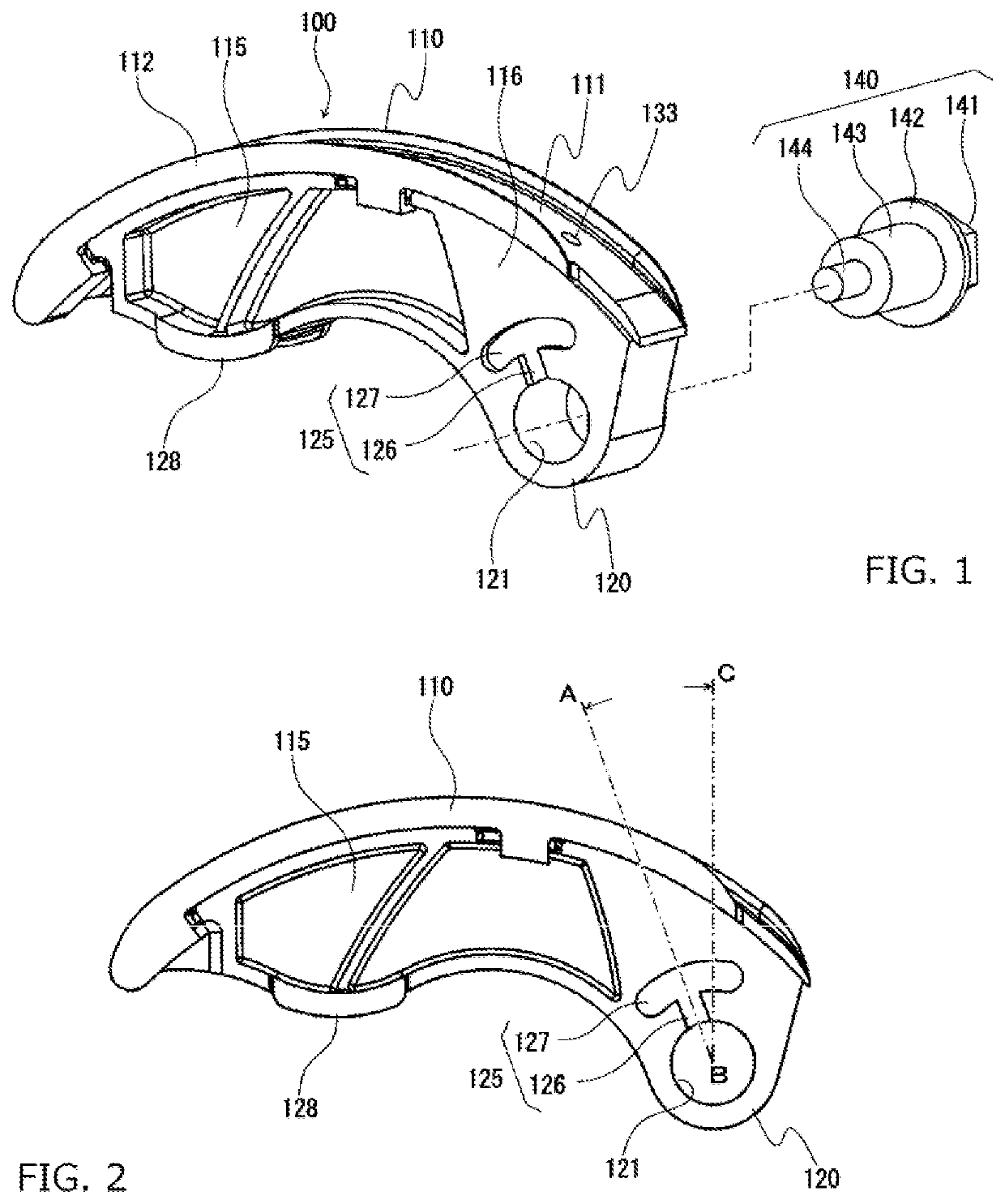
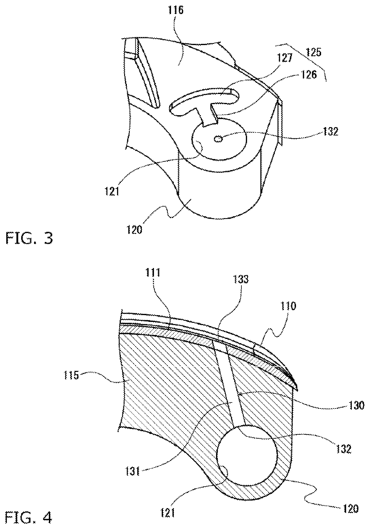
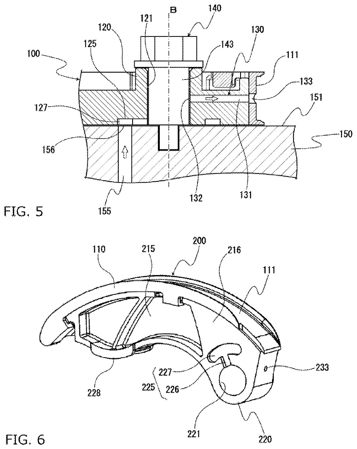
[0042]The chain guide 100 according to a first embodiment of the present invention is configured as a movable guide, attached to an engine block (not shown) such as to be pivotable around a mounting bolt 140 as the pivot shaft and to apply appropriate tension to a chain, cooperating with a hydraulic tensioner (not shown) as illustrated in FIG. 1 to FIG. 4.

[0043]This chain guide 100 has a shoe 110 slidably guiding a running chain, and a base member 115 supporting the shoe 110 along a longitudinal guiding direction (chain running direction). The shoe 110 and base member 115 are made of a synthetic resin material or the like.

[0044]The shoe 110 has a chain running surface (sliding surface) 111 extending along the longitudinal guiding direction, and guide parts 112 standing upright along both edges of the chain running surface 111 in the guide width direction.

[0045]The base member 115 is curved along the longitudinal guiding direction, and has a mounting part 120 near one end of the long...

embodiment 2

[0055]The chain guide according to a second embodiment of the present invention has substantially the same configuration as the chain guide 100 according to the first embodiment described above except for a difference in the configuration of the oil jet passage. The chain guide according to this embodiment is configured as a movable guide, attached to an engine block such as to be pivotable by a mounting bolt to apply appropriate tension to a chain, cooperating with a hydraulic tensioner. This chain guide 200 has a shoe 110 slidably guiding a running chain, and a base member 215 supporting the shoe 110 along a longitudinal guiding direction (chain running direction), as illustrated in FIG. 6 to FIG. 9.

[0056]The base member 215 is curved along the longitudinal guiding direction, and has a mounting part 220 near one end of the longitudinal guiding direction for attaching the chain guide to the engine block, and a tensioner abutment part 228 near the other end for making contact with t...

embodiment 3

[0060]The chain guide according to a third embodiment of the present invention has substantially the same configuration as the chain guide 100 according to the first embodiment described above except for a difference in the configuration of the oil jet passage. The chain guide according to this embodiment is configured as a movable guide, attached to an engine block such as to be pivotable by a mounting bolt to apply appropriate tension to a chain, cooperating with a hydraulic tensioner. This chain guide 300 has a shoe 110 slidably guiding a running chain, and a base member 315 supporting the shoe 110 along a longitudinal guiding direction (chain running direction), as illustrated in FIG. 11 and FIG. 12.

[0061]The base member 315 is curved along the longitudinal guiding direction, and has a mounting part 320 near one end of the longitudinal guiding direction for attaching the chain guide to the engine block, and a tensioner abutment part 328 near the other end for making contact with...


PUM


Abstract

An object of the present invention is to provide a chain guide that can improve functional properties of a chain drive system. The chain guide of the present invention is attached to an engine block by a mounting bolt and slidably guides a running chain. The chain guide includes a mounting part provided with a shaft hole through which a mounting bolt is passed, and an oil jet passage for injecting lubricating oil, supplied to the shaft hole at a predetermined pressure, toward the chain.

Description

BACKGROUND OF THE INVENTION1. Field of the Invention[0001]The present invention relates to, for example, a chain guide provided to a chain drive system incorporated in a timing system of a car engine in order to guide a running chain.2. Description of the Related Art[0002]Conventionally, it is common to use a chain guide that has a guide surface slidably guiding a running chain and a main body supporting the guide surface along a chain running direction in order to stabilize the chain and keep correct tension between sprockets.[0003]For example, as illustrated in FIG. 19, a chain drive system is known that has an endless chain CH passed over a drive sprocket S1 attached to a crankshaft and a pair of driven sprockets S2 attached to cam shafts inside an engine room, with this chain CH being guided by a chain guide.[0004]In this known chain drive system, a chain guide (movable guide) SG having a slider function is disposed on the outer side of a part of the chain CH that is the slack s...

Claims


Application Information

Patent Timeline
Patent Type & Authority Applications(United States)
IPC IPC(8): F16H57/05F16H7/18F16H57/04F01L1/02F01M11/02
CPCF16H57/05F16H7/18F01M11/02F01L1/022F16H57/042F16H7/06F16H57/0456F16H57/028F16N2210/33F16N7/14F16N7/24F01M9/10F02B67/06F01M1/08F02F2007/0041
Inventor SHIMOSAKA, KOICHI
Owner TSUBAKIMOTO CHAIN CO
Why Eureka
Try Eureka