Female terminal

a terminal and female technology, applied in the field of female terminals, can solve the problems of inability to use springs and one spring becomes useless, and achieve the effects of preventing incorrect insertion of spring contacts, reliable fixing parts, and efficient operation

Active Publication Date: 2016-08-04
YAZAKI CORP
View PDF7 Cites 2 Cited by
  • Summary
  • Abstract
  • Description
  • Claims
  • Application Information

AI Technical Summary

Benefits of technology

[0038]According to the above-described invention (1), since the long plate spring piece of the cylindrical spring contact is not disposed on the cylindrical joint of the female terminal main body, it is possible to efficiently use all of the springs as a point of contact.
[0039]According to the above-described invention (2), the fixing part and the locking part are respectively formed to be laterally asymmetrical. Therefore, when all of the locking parts are fixed to all of the fixing parts, since the void part of the joint of the spring contact is generated at the joint of the spring accommodation part, it is possible to prevent incorrect insertion of the spring contact into the female terminal main body.
[0040]According to the above-described invention (3), since the fixing part is formed by notching the end part of the female terminal main body, it is possible to simply make a reliable fixing part.
[0041]According to the above-described invention (4), since the locking part is formed by folding the end part of the male terminal insertion side of the spring contact to the outside, it is possible to simply make a reliable locking part.

Problems solved by technology

However, since the performance of the long plate spring piece 130L on the joint110T as a point of contact cannot be ensured, one spring becomes useless, and a case where all of the springs cannot be used as a point of contact is generated.

Method used


Image

  • Female terminal
  • Female terminal
  • Female terminal

Examples


Embodiment Construction

[0048]Hereinafter, a female terminal of the present invention will be described based on FIGS. 1(A) to 3(B).

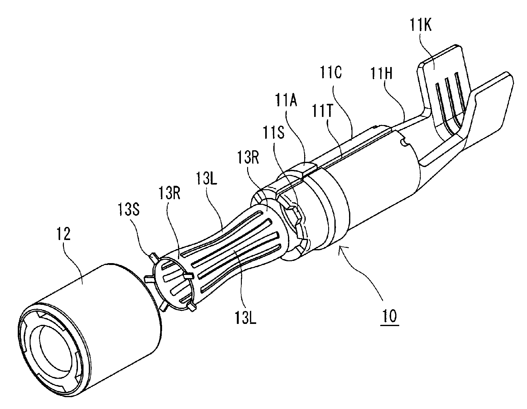
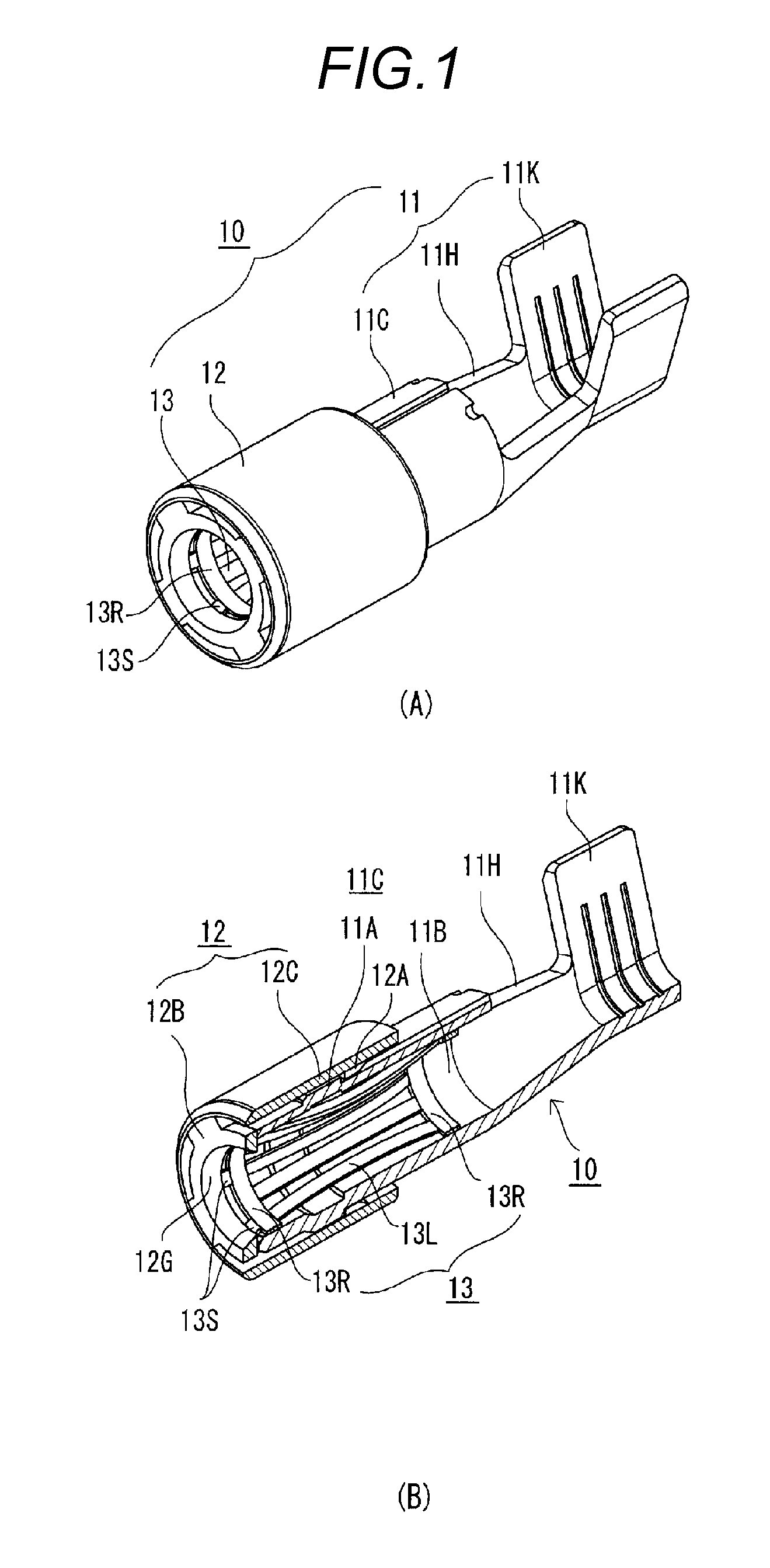
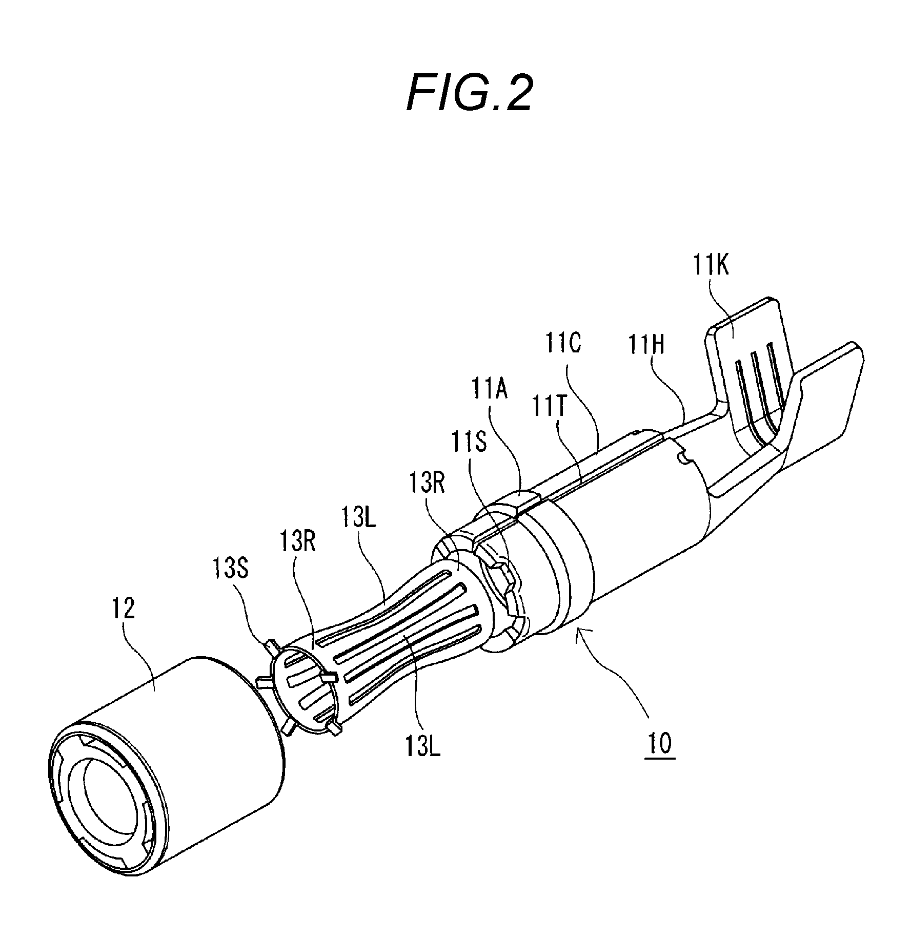
[0049]FIG. 1(A) is a perspective view of the female terminal according to the present invention, and FIG. 1(B) is a longitudinal sectional view cut along an axial direction of the female terminal of FIG. 1(A). FIG. 2 is an exploded perspective view of the female terminal of FIG. 1(A).

[0050]In FIG. 1(A), a female terminal 10 is made of a female terminal main body 11, a resin cap 12, and a spring contact 13.

[0051]Both the female terminal main body 11 and the spring contact 13 are formed by punching a metal plate, and the female terminal main body 11 is formed to be rounded in a cylindrical shape by press working so that one end surface 14 and the other end surface 15 abut against each other. The resin cap 12 is formed by a synthetic resin by injection.

[0052]In addition, the spring contact 130 is formed to be rounded in a cylindrical shape so that one end surface 16 and the other...


PUM


Abstract

A locking part (13S) which is formed in an end part of a male terminal insertion side of a spring contact is fixed to a fixing part (11S) which is formed in an end part of a female terminal main body (11), and in this state, a joint (11T) at which one end surface and the other end surface which are positioned in a circumferential direction of the female terminal main body face each other, and a joint (T) at which one end surface and the other end surface which are positioned in a circumferential direction of a spring contact (13) each other, are positioned to overlap each other in a radial direction.

Description

TECHNICAL FIELD[0001]The present invention relates to a female terminal used in a connector which is used in connecting various types of machines loaded in an electric vehicle or a hybrid vehicle, and particularly to a female terminal in which a cylindrical spring contact which comes into contact with the corresponding male terminal is provided in a terminal main body.BACKGROUND ART[0002]As a female terminal in the related art, a female terminal described in Patent literature 1 is known. FIG. 4(A) is a perspective view of a female terminal described in Patent literature 1, and FIG. 4(B) is a longitudinal sectional view cut along an axial direction of the female terminal of FIG. 4(A). FIG. 5 is an exploded perspective view of the female terminal of FIG. 4(A).[0003]In FIG. 4(A), a female terminal 100 is made of a female terminal main body 110, a cap 120, and a spring contact 130. Both the female terminal main body 110 and the spring contact 130 are formed by punching a metal plate, an...

Claims


Application Information

Patent Timeline
Patent Type & Authority Applications(United States)
IPC IPC(8): H01R13/11
CPCH01R13/187H01R4/184H01R13/111H01R2101/00H01R24/20
Inventor YOSHIOKA, TOSHIKAZUYAMADA, YUYA
Owner YAZAKI CORP
Why Eureka
Try Eureka