Tensioning device

Active Publication Date: 2020-06-04
TOHNICHI MFG
View PDF0 Cites 0 Cited by
  • Summary
  • Abstract
  • Description
  • Claims
  • Application Information

AI Technical Summary

Benefits of technology

The present invention is about a device that is used to tension bolts. The device has a female thread part and a male thread part that is formed on the outer surface of a washer. This ensures that the bolt is tensioned through the washer and prevents any loss of accuracy in detecting the force applied to the bolt. This improves the accuracy of the tensioning process.

Problems solved by technology

After the tightening, there are seldom chances of controlling the tightening force.
However, there may cause the bolt to be loosened owing to unexpected external force in operation of the machine to lower the tightening force.
This may considerably increase the risk of fatigue fracture.

Method used


Image

  • Tensioning device
  • Tensioning device
  • Tensioning device

Examples


first embodiment

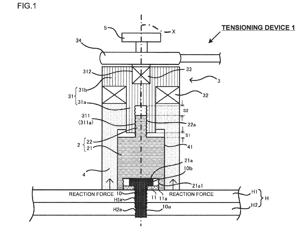
[0023]A tensioning device of this embodiment serves to fasten a fastened member with a bolt and a washer, and applies tension to the bolt via the washer while holding the upper surface of the fastened member. The tensioning device is used for detection of the axial force of the bolt (in other words, fastening force of the bolt), and detection of the spring constant of the fastened member to which the bolt is fastened. The basic concept of the axial force detection is similar to the one disclosed in Japanese Patent No. 4028254. In the following embodiments, structures and operations of the tensioning devices will be described by taking the axial force detection as an example.

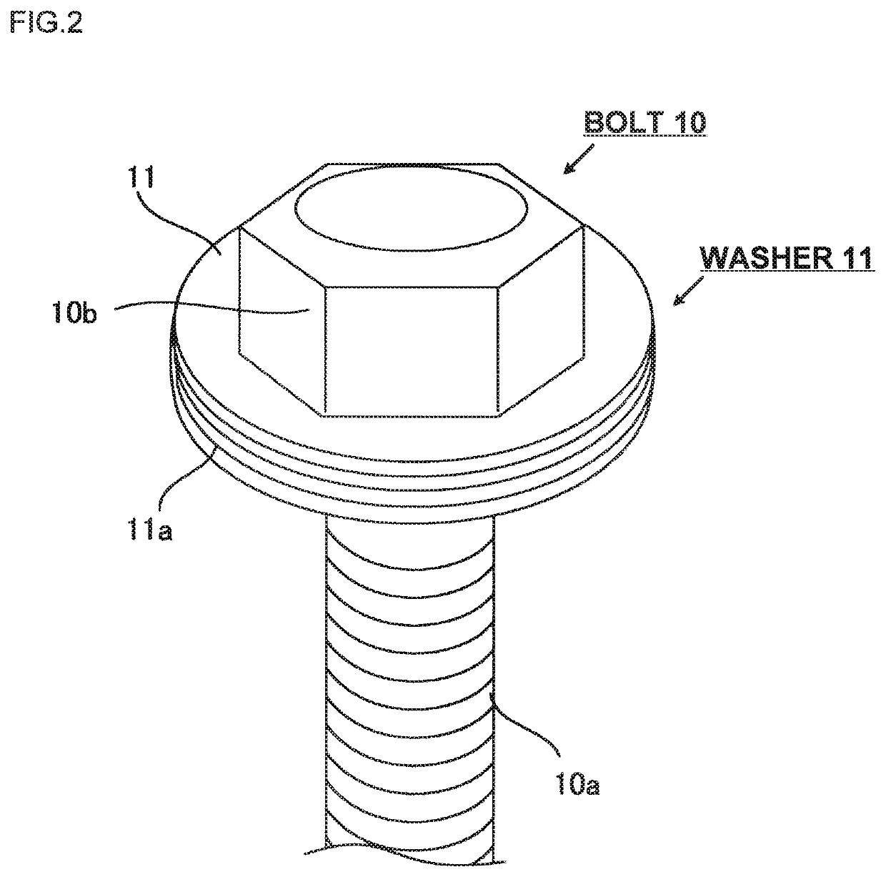
[0024]FIG. 1 is a schematic view of a tensioning device of the embodiment in the state just after starting tensioning the washer. A plurality of members constituting the tensioning device are marked with mutually different hatchings so as to clarify each boundary among those members. FIG. 2 is a perspective view ...

second embodiment

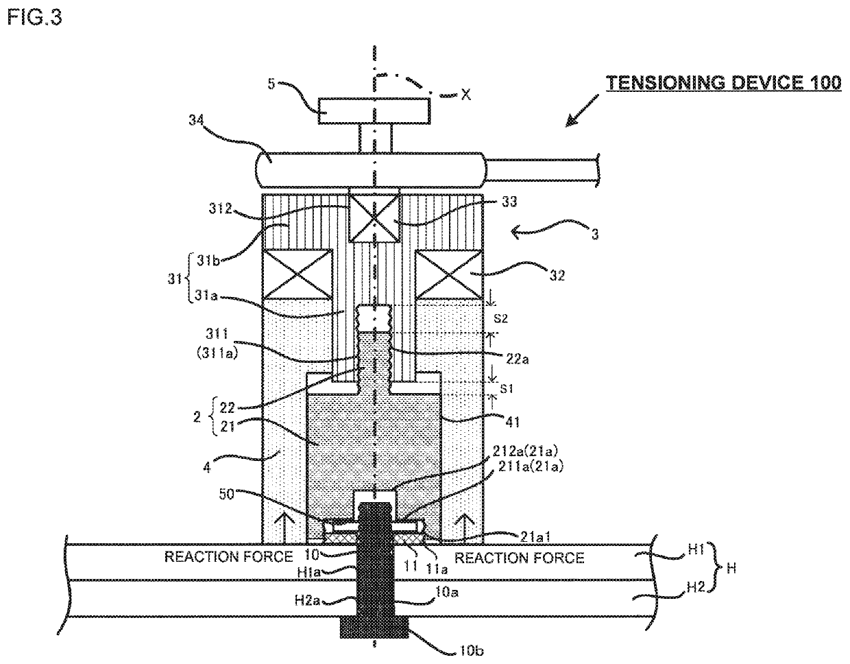
[0054]A tensioning device 100 of the present embodiment will be described referring to FIG. 3. FIG. 3 corresponding to FIG. 1 represents the state just after abutment of the tension bearer 4 on the fastened body H1. A detailed explanation of the structure similar to the one described in the first embodiment will be omitted. The bolt 10 of the embodiment has the bolt head 10b in contact with a lower surface of the fastened body H2. The top end of the bolt shaft 10a protrudes from the upper surface of the fastened body H1. That is, the bolt is in the direction opposite to the direction of the bolt of the first embodiment. The bolt holes H1a and H2a are not threaded.

[0055]The washer 11 is insertedly fitted with the protruding portion of the bolt shaft 10a, to which a nut 50 is fastened from above the washer 11. That is, the washer 11 is clamped between the fastened body H1 and the nut 50. The washer 11 has the outer diameter dimension set to be larger than that of the nut 50.

[0056]Like...

third embodiment

Modified Example of Third Embodiment

[0070]In the third embodiment, the bolt flange 13c has a flat shape. However, the present invention is not limited to the above-described example, but applicable to any shape, instead of the flat shape, having the radially and outwardly extended diameter from the bolt head 13b in a non-restricted manner. For example, the bolt flange 13c may be formed to have a curved surface (or tapered surface) as shown in FIG. 8 to be described later. In such a case, the large-diameter hollow portion 211a and the small-diameter hollow portion 212a of the connection member 2 may be shaped to satisfy the conditions 1 and 2 in abutment on the curved surface (or tapered surface) of the bolt flange. The concave or the convex portion formed on the curved surface or the tapered surface, if any, may be considered as the abutment part.


PUM


Abstract

An error of an axial force detection is reduced by tensioning a bolt with a tensioning device engaged with a part of the bolt, different from a shaft portion of the bolt. A tensioning device is configured to apply upward tension to a bolt fastened to a fastened member H, and fitted with a washer. A first male thread portion is formed on an outer circumferential surface of the washer. The tensioning device includes a connection member having a first female thread portion to be engaged with the first male thread portion, a tensioning mechanism for tensioning the connection member in a state where the first male thread portion is engaged with the first female thread portion, and a tension bearer which is disposed around an outer circumference of the connection member, and bears a reaction force applied from the fastened member H in tensioning performed by the tensioning mechanism.

Description

TECHNICAL FIELD[0001]The present invention relates to a tensioning device which applies tension upwardly to a bolt fastened to a fastened member.BACKGROUND ART[0002]Machines such as automobiles, and structures such as bridges are assembled through fastening with screws. The strength of the screw as the fastener largely relies on the tightening force. Meanwhile, monitoring of the fastening force applied to the bolt fasteners is performed by measuring the torque and the rotation only during tightening of them. After the tightening, there are seldom chances of controlling the tightening force. However, there may cause the bolt to be loosened owing to unexpected external force in operation of the machine to lower the tightening force. This may considerably increase the risk of fatigue fracture. It is therefore necessary to pay attention to detection of the tightening force applied to the fastened bolt in order to prevent the rupture accident of the bolt, and improve reliability of the s...

Claims


Application Information

Patent Timeline
IPC IPC(8): F16B31/02B25B29/02F16B43/00
CPCF16B43/00B25B29/02F16B31/028G01L5/243F16B31/02
Inventor KOMATSU, KYOICHITSUJI, HIROSHITSUJI, OSAMUITO, SEIJI
Owner TOHNICHI MFG
Why Eureka
Try Eureka