Tensioning device
a technology of a stent and a bolt is applied in the direction of force/torque/work measurement apparatus, instruments, washing machines, etc., which can solve the problems of reducing affecting the accuracy of detection, and loosing the bolt, so as to reduce the chance of controlling the tightening force. , to achieve the effect of suppressing the deterioration of detection accuracy
- Summary
- Abstract
- Description
- Claims
- Application Information
AI Technical Summary
Benefits of technology
Problems solved by technology
Method used
Image
Examples
first embodiment
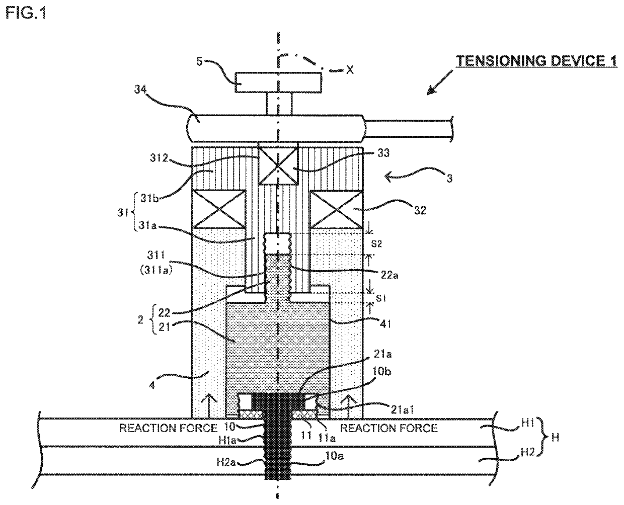
[0025]A tensioning device of this embodiment serves to fasten a fastened member with a bolt and a washer, and applies tension to the bolt via the washer while holding the upper surface of the fastened member. The tensioning device is used for detection of the axial force of the bolt (in other words, fastening force of the bolt), and detection of the spring constant of the fastened member to which the bolt is fastened. The basic concept of the axial force detection is similar to the one disclosed in Japanese Patent No. 4028254. In the following embodiments, structures and operations of the tensioning devices will be described by taking the axial force detection as an example.
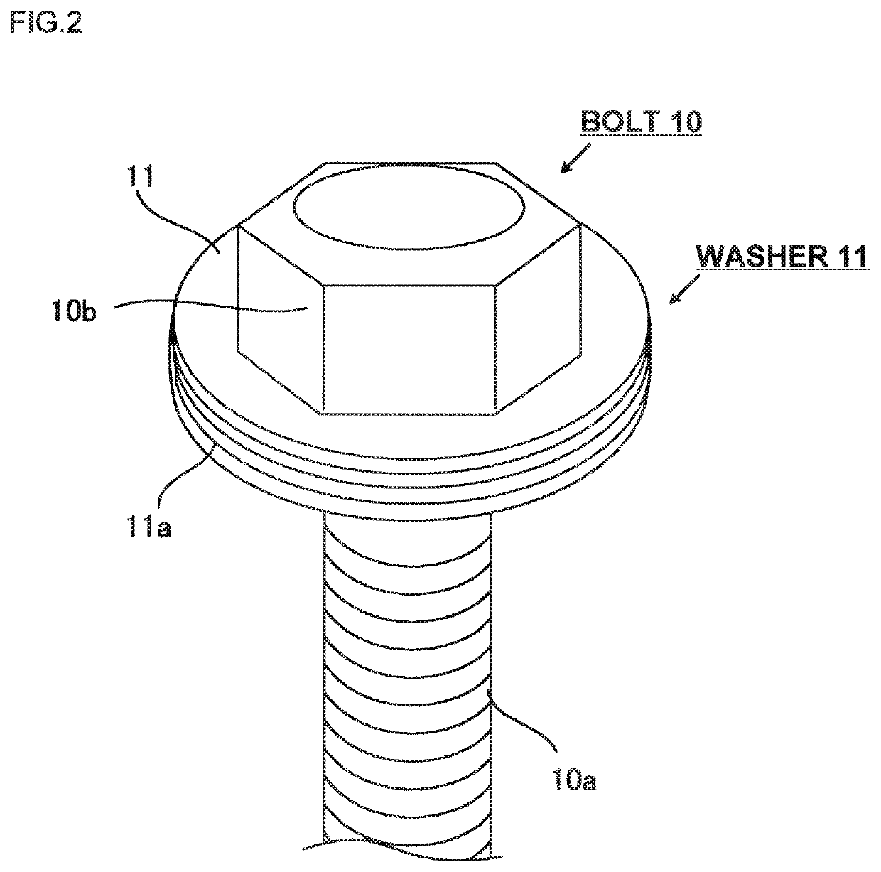
[0026]FIG. 1 is a schematic view of a tensioning device of the embodiment in the state just after starting tensioning the washer. A plurality of members constituting the tensioning device are marked with mutually different hatchings so as to clarify each boundary among those members. FIG. 2 is a perspective view ...
second embodiment
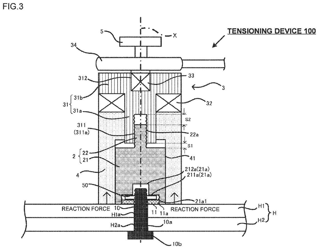
[0056]A tensioning device 100 of the present embodiment will be described referring to FIG. 3. FIG. 3 corresponding to FIG. 1 represents the state just after abutment of the tension bearer 4 on the fastened body H1. A detailed explanation of the structure similar to the one described in the first embodiment will be omitted. The bolt 10 of the embodiment has the bolt head 10b in contact with a lower surface of the fastened body H2. The top end of the bolt shaft 10a protrudes from the upper surface of the fastened body H1. That is, the bolt is in the direction opposite to the direction of the bolt of the first embodiment. The bolt holes H1a and H2a are not threaded.
[0057]The washer 11 is insertedly fitted with the protruding portion of the bolt shaft 10a, to which a nut 50 is fastened from above the washer 11. That is, the washer 11 is clamped between the fastened body H1 and the nut 50. The washer 11 has the outer diameter dimension set to be larger than that of the nut 50.
[0058]Like...
third embodiment
Modified Example of Third Embodiment
[0072]In the third embodiment, the bolt flange 13c has a flat shape. However, the present invention is not limited to the above-described example, but applicable to any shape, instead of the flat shape, having the radially and outwardly extended diameter from the bolt head 13b in a non-restricted manner. For example, the bolt flange 13c may be formed to have a curved surface (or tapered surface) as shown in FIG. 8 to be described later. In such a case, the large-diameter hollow portion 211a and the small-diameter hollow portion 212a of the connection member 2 may be shaped to satisfy the conditions 1 and 2 in abutment on the curved surface (or tapered surface) of the bolt flange. The concave or the convex portion formed on the curved surface or the tapered surface, if any, may be considered as the abutment part.
PUM
 Abstract
Description
Claims
Application Information
 - R&D
- Intellectual Property
- Life Sciences
- Materials
- Tech Scout
- Unparalleled Data Quality
- Higher Quality Content
- 60% Fewer Hallucinations
Browse by: Latest US Patents, China's latest patents, Technical Efficacy Thesaurus, Application Domain, Technology Topic, Popular Technical Reports.
© 2025 PatSnap. All rights reserved.Legal|Privacy policy|Modern Slavery Act Transparency Statement|Sitemap|About US| Contact US: help@patsnap.com


