

Showers
- Summary
- Abstract
- Description
- Claims
- Application Information
AI Technical Summary
Benefits of technology
Problems solved by technology
Method used
Image

Examples
first embodiment
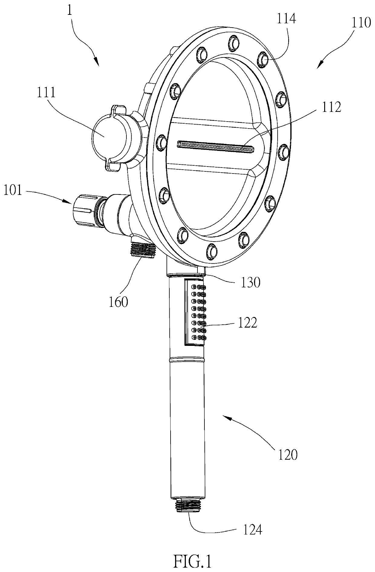
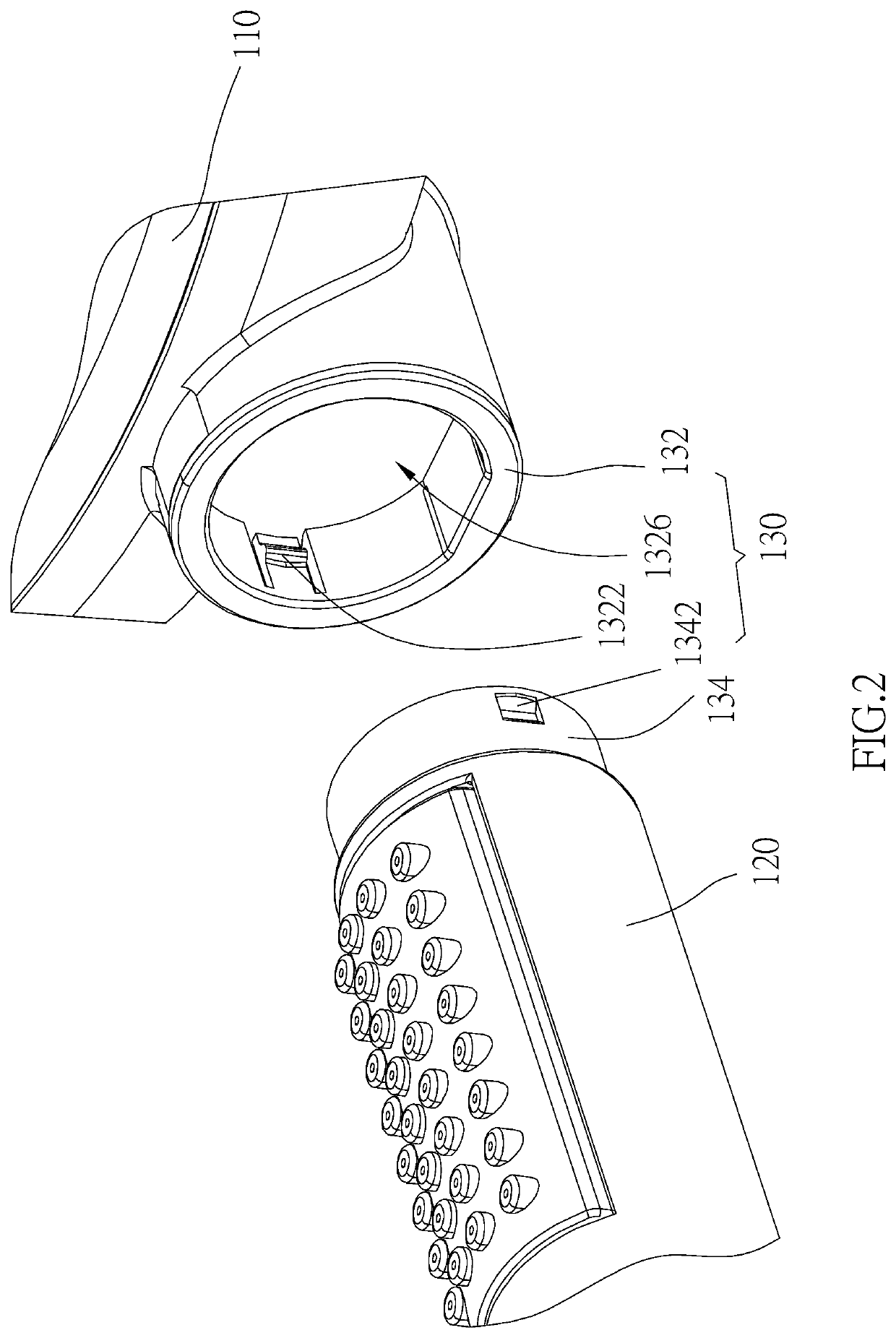
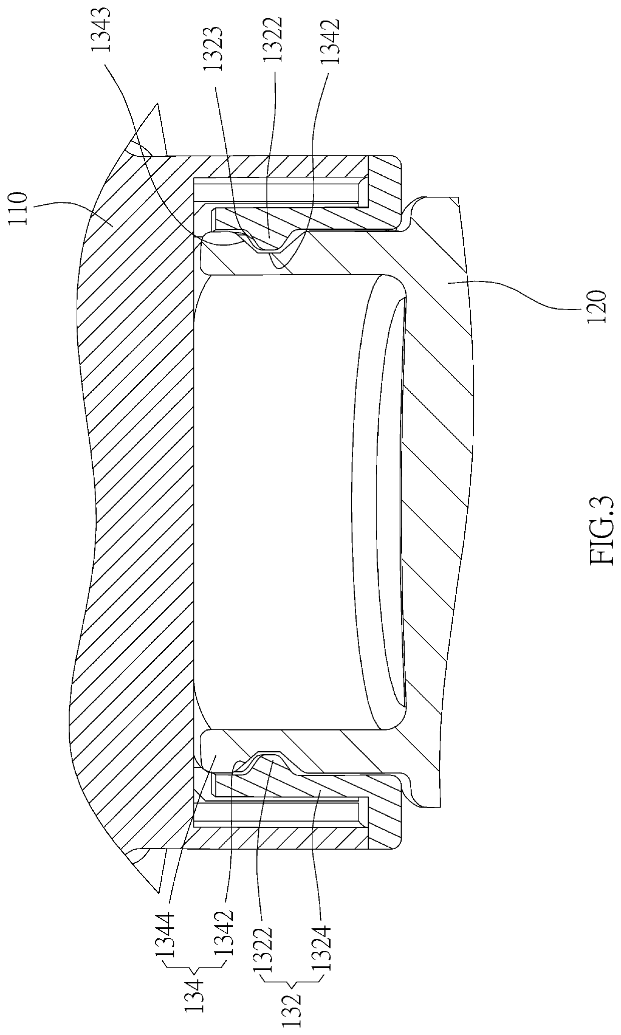
[0021]As illustrated in FIG. 1 to FIG. 3, a shower 1 in accordance with the present disclosure is provided, including a first shower member 110, a second shower member 120 and a connecting assembly 130.
[0022]The first shower member 110 has an inlet opening 101 and first outlet openings 112, 114, 116, wherein the inlet opening 101 communicates with the first outlet opening 112, 114, 116. The second shower member 120 is connected to the first shower member 110, and has a second outlet opening 122, wherein the second outlet opening 122 communicates with the inlet opening 101. In the first embodiment of the present disclosure, the second shower member 120 has an inlet opening 124 communicating with the first outlet openings 116 of the first shower member 110 through a hose (not shown), whereby to communicate the second outlet opening 122 with the inlet opening 101.
[0023]The connecting assembly 130 includes a first connecting unit 132 and a second connecting unit 134. The first connectin...
second embodiment
[0031]As illustrated in FIG. 4 to FIG. 7, a shower 2 in accordance with the present disclosure is provided, including a first shower member 210, a second shower member 220 and a connecting assembly 230.
[0032]The connecting assembly 230 includes a first connecting unit 232 and a second connecting unit 234. The first connecting unit 232 is positioned on the first shower member 210. The second connecting unit 234 is positioned on the second shower member 220. The first connecting unit 232 and the second connecting unit 234 are detachably connected to each other. In fact, the first connecting unit 232 could be positioned on the second shower member 220, and the second connecting unit 234 could be positioned on the first shower member 210, either.
[0033]In the second embodiment of the present disclosure, the first connecting unit 232 includes protrusions 2322, and the second connecting unit 234 includes recesses 2342, wherein the protrusions 2322 are respectively detachably positioned in ...
third embodiment
[0042]As illustrated in FIG. 8 to FIG. 9, a shower 3 in accordance with the present disclosure is provided, including a first shower member 310, a second shower member 320 and a connecting assembly 330.
[0043]The connecting assembly 330 includes a first connecting unit 332 and a second connecting unit 334. The first connecting unit 332 is positioned on the first shower member 310. The second connecting unit 334 is positioned on the second shower member 320. The first connecting unit 332 and the second connecting unit 334 are detachably connected to each other. In fact, the first connecting unit 332 could be positioned on the second shower member 320, and the second connecting unit 334 could be positioned on the first shower member 310, either.
[0044]In the third embodiment of the present disclosure, the first connecting unit 332 includes protrusions 3322, and the second connecting unit 334 includes recesses 3342, wherein the protrusions 3322 are respectively detachably positioned in t...
PUM
 Abstract
Description
Claims
Application Information