

Tool suspension device
- Summary
- Abstract
- Description
- Claims
- Application Information
AI Technical Summary
Benefits of technology
Problems solved by technology
Method used
Image

Examples
Embodiment Construction
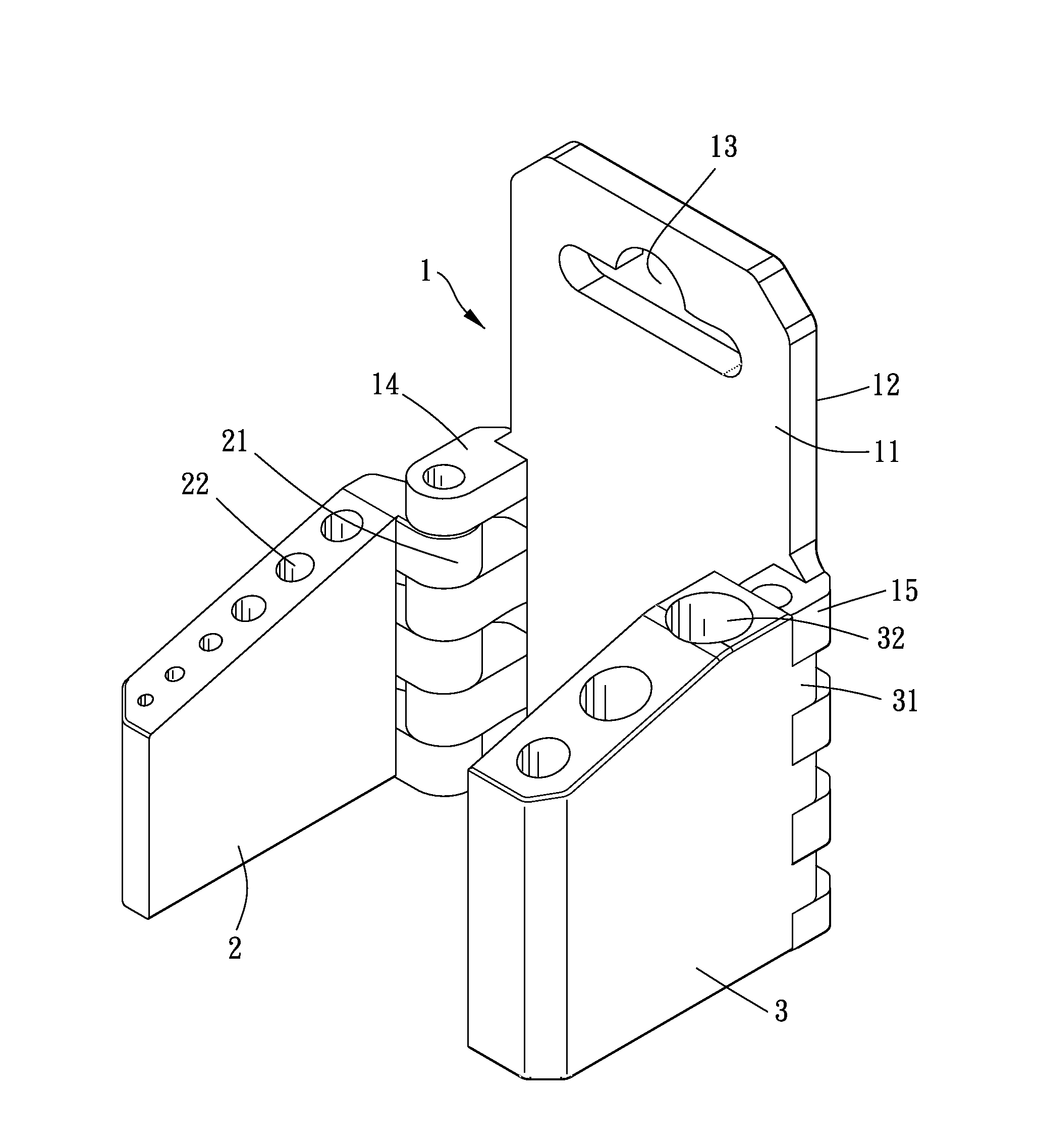
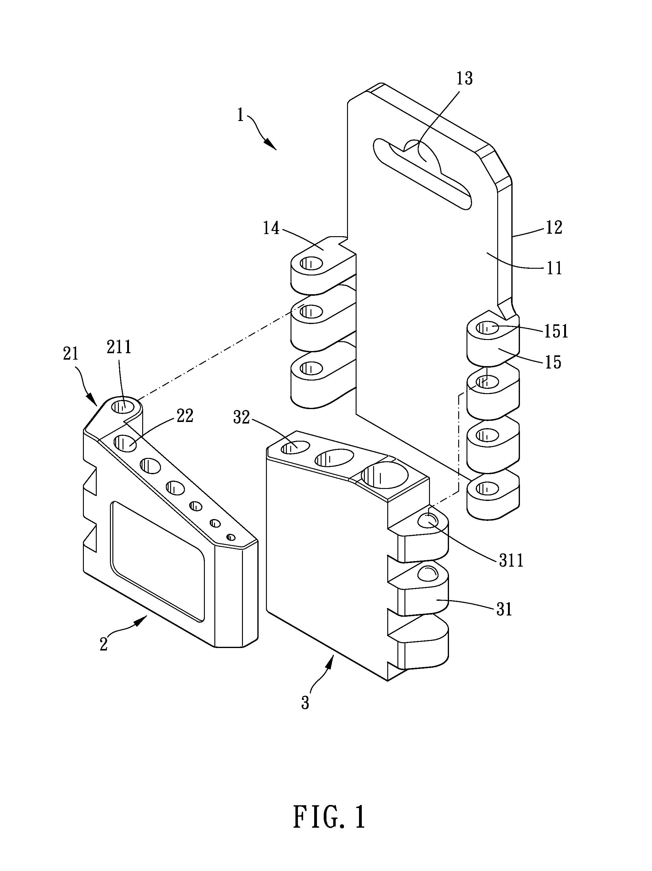
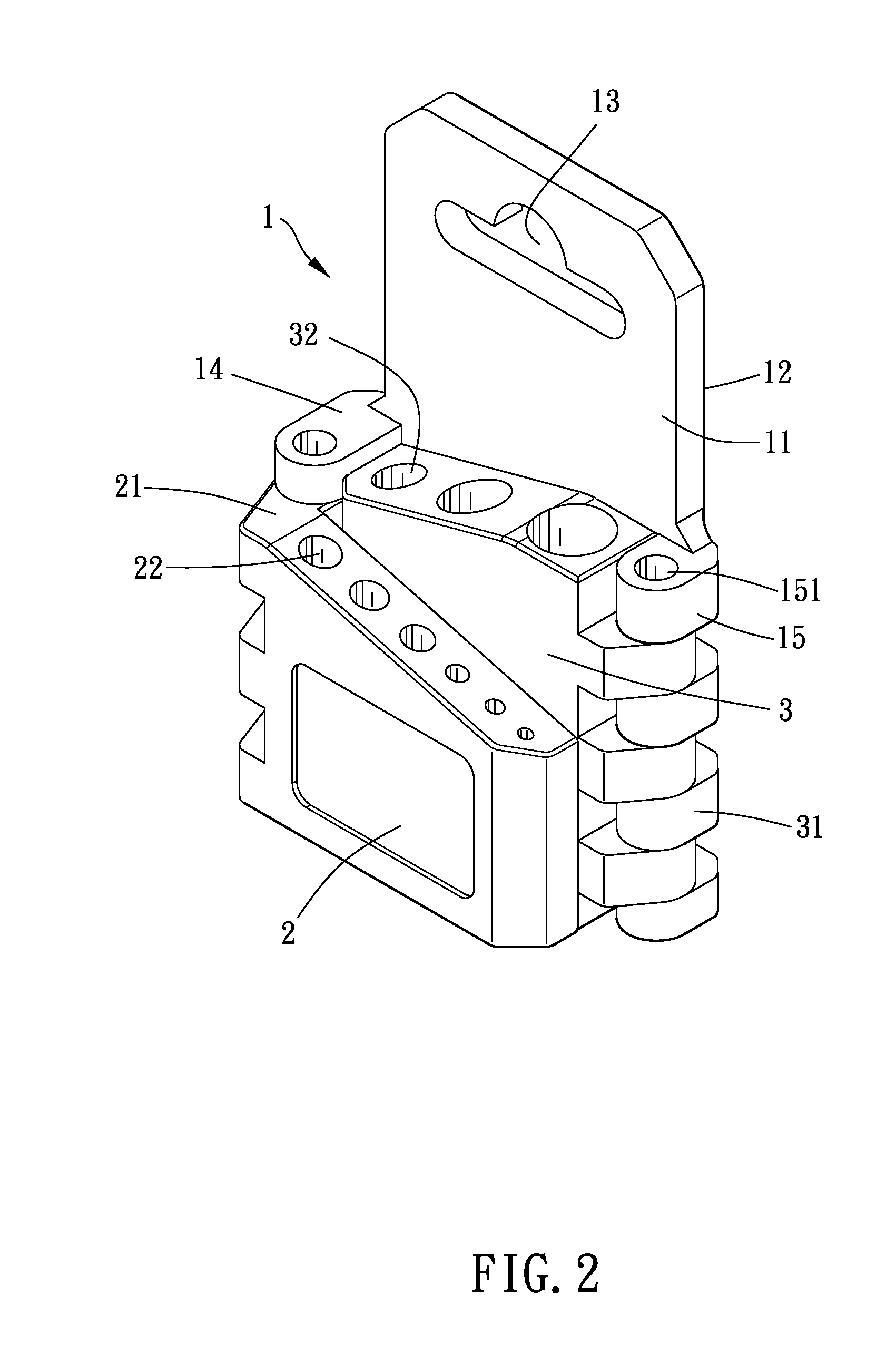
[0018]Please refer to FIG. 1 to FIG. 5 for a major embodiment of the present invention. The suspension device of the present invention includes a suspension member 1, a first receiving member 2, and a second receiving member 3.
[0019]The suspension member 1 has a first face 11 and an opposite second face 12. The suspension member 1 is formed with a first pivot structure and a second pivot structure which are protruded from the first face away from the second face. In the present embodiment, the suspension member 1 is plate-shaped, and the suspension member 1 is formed with a suspension portion 13 for suspension. Preferably, the suspension portion 13 is an elongated hole for being suspended on a hook or other device. Optionally, the suspension portion can be a hook or similar device. The first pivot structure and the second structure are located at two opposite ends of a same side of the suspension member 1 respectively. The first pivot structure is defined with a first pivot axis, an...
PUM
 Abstract
Description
Claims
Application Information