Electric Stimulator

Active Publication Date: 2017-03-16
LI RICHARD
View PDF0 Cites 3 Cited by
  • Summary
  • Abstract
  • Description
  • Claims
  • Application Information

AI Technical Summary

Benefits of technology

[0004]In view of the drawbacks of the conventional electric stimulators that wires are exposed, easy storage may not be possible, neat and organized management may not be allowed, application to small area portions is not possible, detachment may easily occur, adhesion may be lost and waste results, and stimulation can be generated for a fixed site, making the use thereof inconvenient, the present invention aims to provide an electric simulator, which comprises a housing, a control circuit board, and at least two electrode plates. The housing comprises an internal space formed therein and an outside surface in which at least one electrode plate retention slot is formed. The control circuit board is mounted in the internal space of the housing to control intensity and frequency of a current output. The electrode plates are elec

Problems solved by technology

For example, there must be electric wires between the electrotherapeutic patch and the equipment and thus, problems that the wires are exposed and may not be easily stowed and may not allow for neat and organized management occur.
Further, the electrotherapeutic patch can only be attached to the skin at a site where a sufficient surface area is available and is not fit for small-area portions (such as the periphery of an eye, a corner of a mouth, and a forehead).
Furt

Method used


Image

  • Electric Stimulator
  • Electric Stimulator
  • Electric Stimulator

Examples


Embodiment Construction

[0013]The following descriptions are exemplary embodiments only, and are not intended to limit the scope, applicability or configuration of the invention in any way. Rather, the following description provides a convenient illustration for implementing exemplary embodiments of the invention. Various changes to the described embodiments may be made in the function and arrangement of the elements described without departing from the scope of the invention as set forth in the appended claims.

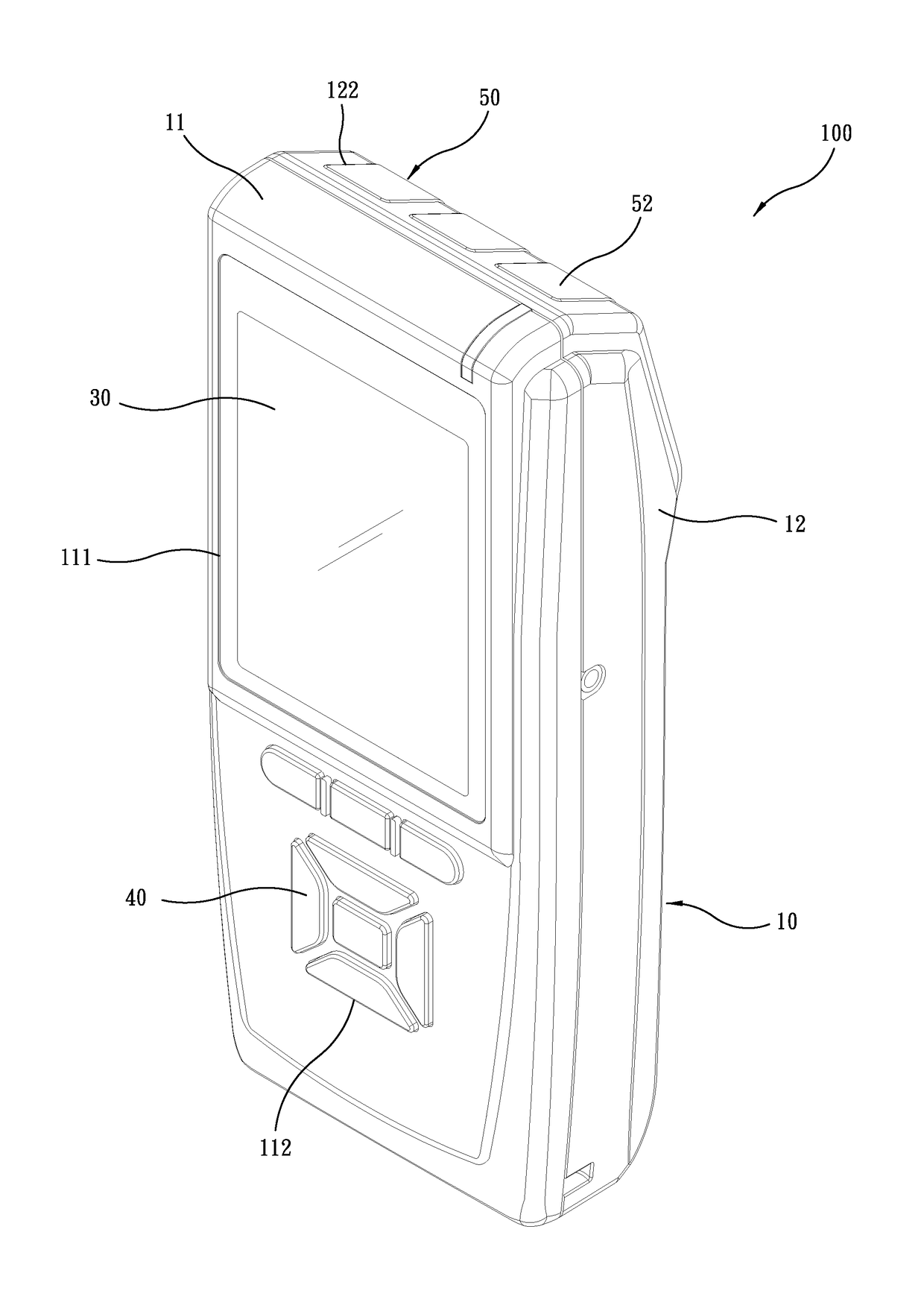
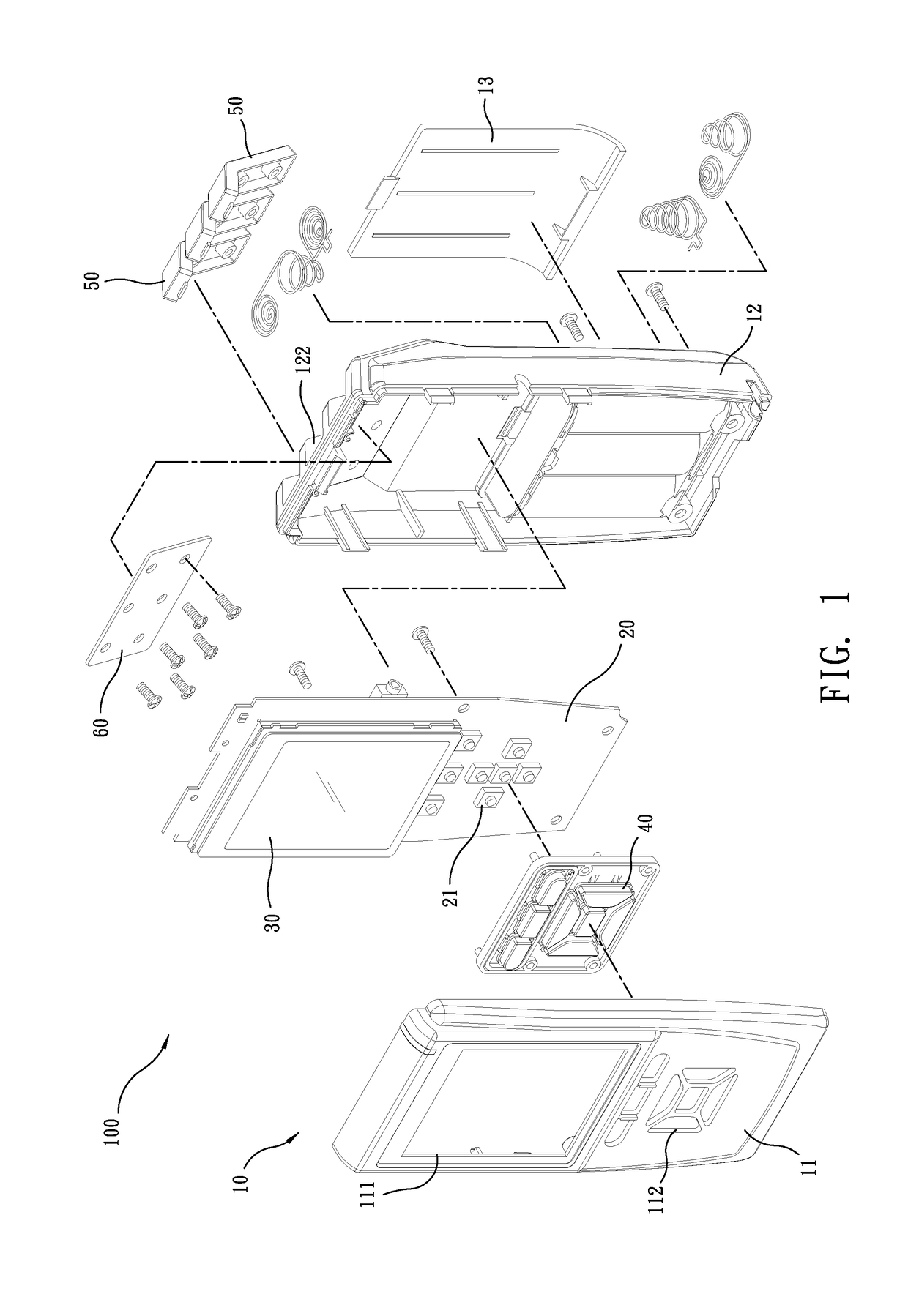
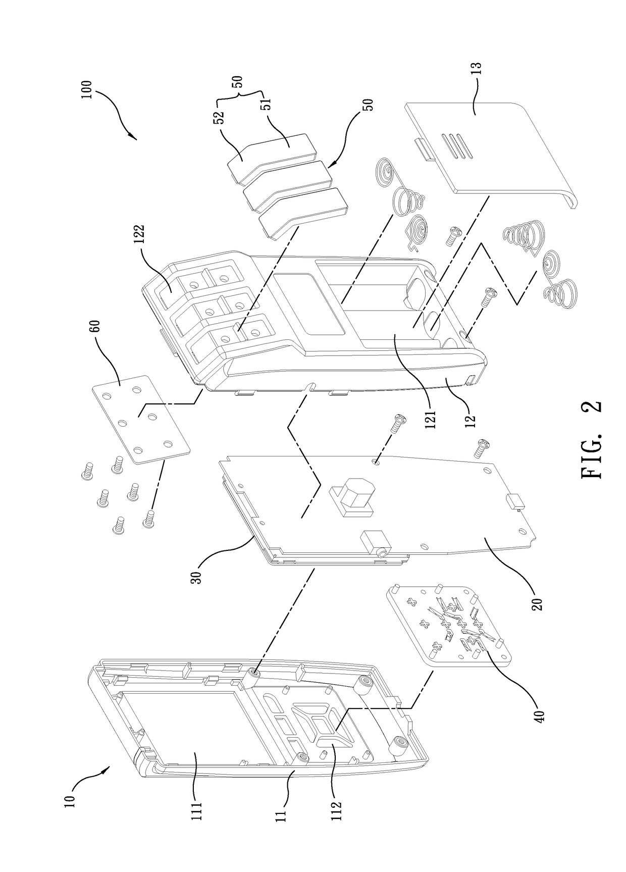
[0014]Referring to FIGS. 1-6, a preferred embodiment of the present invention provides an electric stimulator 100, which generally comprises a housing 10, a control circuit board 20, a display screen 30, a pushbutton cover 40, a plurality of electrode plates 50, and a transmission interface circuit board 60.

[0015]Referring to FIGS. 1-6, the housing 10 comprises a front casing member 11, a rear casing member 12, and a battery lid 13. The front casing member 11 mates and is coupled to the rear casing ...


PUM


Abstract

An electric stimulator includes a housing, a control circuit board, and at least two electrode plates. The housing includes an internal space formed therein and an outside surface in which at least one electrode plate retention slot is formed. The control circuit board is mounted in the internal space of the housing to control intensity and frequency of a current output. The electrode plates are electrically conductive and are received in the electrode plate retention slot of the housing and are in electric connection with the control circuit board. The electrode plates have an outside surface including a large-area contact surface and a small-area contact surface connected to the large-area contact surface. The large-area contact surface has a surface area greater than that of the small-area contact surface. The large-area contact surface and the small-area contact surface define therebetween an inclined angle that is not equal to 180 degrees.

Description

TECHNICAL FIELD OF THE INVENTION[0001]The present invention relates generally to physical electric stimulation equipment, and more particularly to an electric stimulator.DESCRIPTION OF THE PRIOR ART[0002]An electric simulator is a device that generates electric energy signals similar to what generated by a human nervous system and the signal is transmitted to a human body by means of an electrotherapeutic patch that is attached to a surface of the human skin in order to stimulate the nervous system of the human body so that the muscle groups around the electrode may generate a series of localized non-autonomic contraction thereby achieving a desired physical therapeutic effect.[0003]Most of the conventional electric stimulators are connected to the surface of human skin by means of an electrotherapeutic patch. Such an electrotherapeutic patch suffers several drawbacks. For example, there must be electric wires between the electrotherapeutic patch and the equipment and thus, problems...

Claims


Application Information

Patent Timeline
IPC IPC(8): A61N1/36
CPCA61N1/36014A61N1/3603
Inventor LI, RICHARD
Owner LI RICHARD
Why Eureka
Try Eureka