Storage apparatus

Inactive Publication Date: 2005-03-03
LU PO YU
View PDF7 Cites 13 Cited by
  • Summary
  • Abstract
  • Description
  • Claims
  • Application Information

AI Technical Summary

Benefits of technology

[0004] The primary objective of the present invention is to provide a storage apparatus in which tools can be securely stored and from which the tools can be conveniently taken for use.

Problems solved by technology

However, if the stops 231 are too high, it is difficult for a user to take the columns E from the holes 24.

Method used


Image

  • Storage apparatus
  • Storage apparatus
  • Storage apparatus

Examples


first embodiment

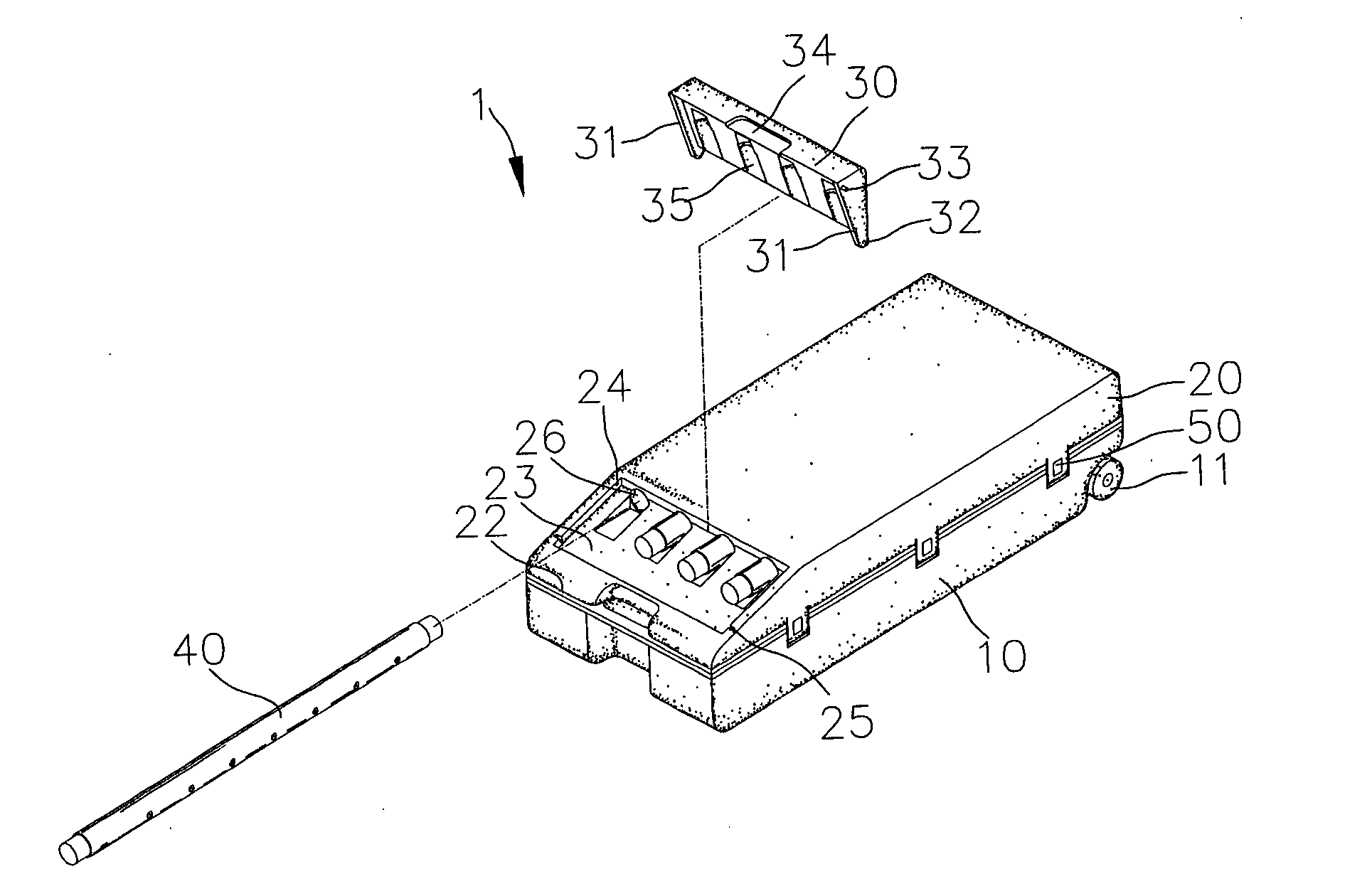
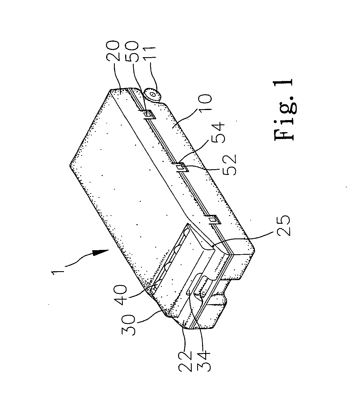
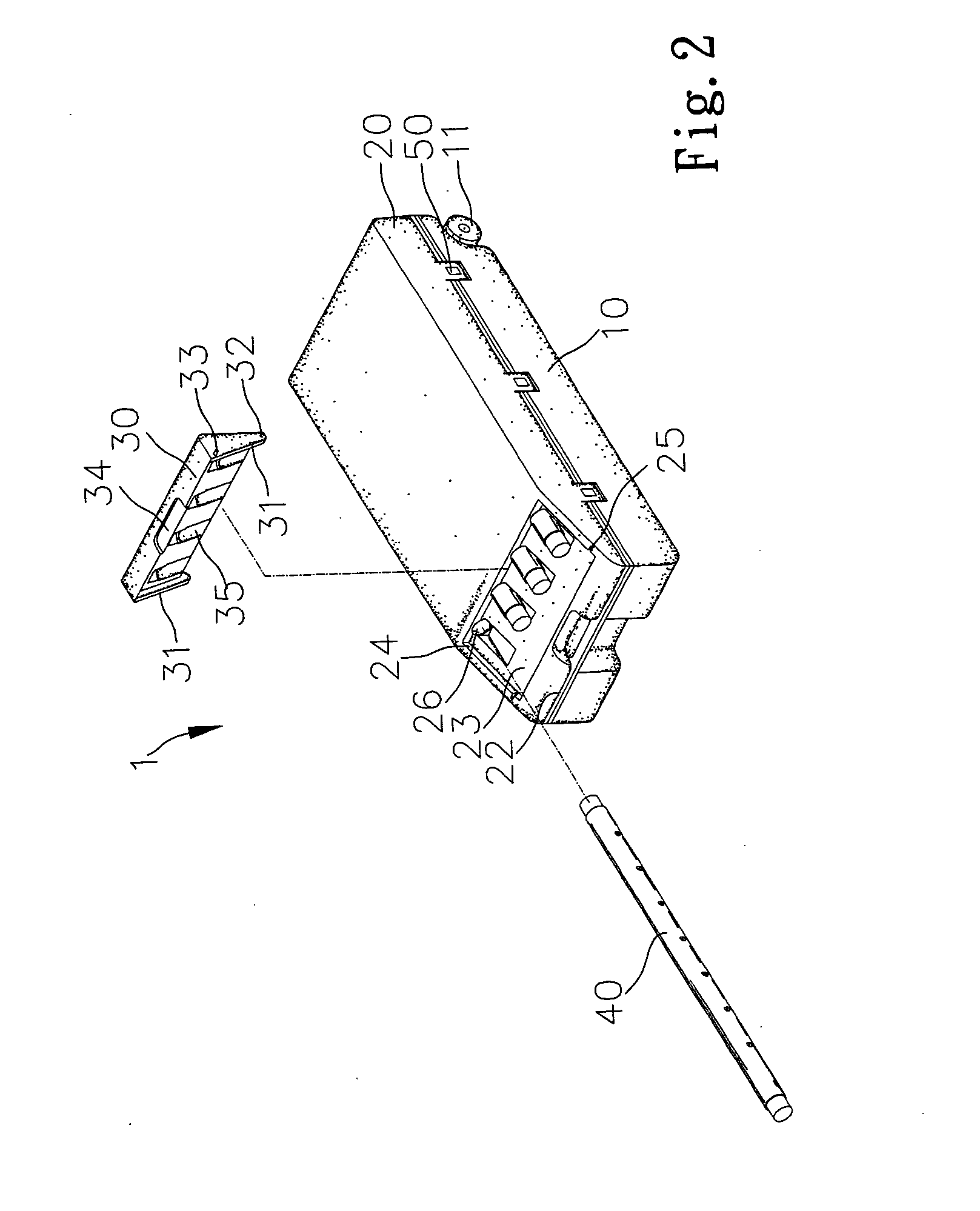
[0014] Referring to FIGS. 1 to 3, according to the present invention, a storage apparatus 1 includes a box 10, a first cover 20 pivotally connected with the box 10 and a second cover 30 pivotally connected with the first cover 20.

[0015] The box 10 includes a space (not shown) defined therein. The space is used for receiving various tools. The box 10 is equipped with two wheels 11.

[0016] Several snap locks 50 are provided to lock the first cover 20 to the box 10.

[0017] The first cover 20 includes a bevel face 22 formed on a front side. The bevel face 22 of the first cover 20 includes a recess 23 defined therein for receiving the second cover 30. Two opposite walls of the recess 23 both include a bearing hole 24 and positioning hole 25. The first cover 20 includes a plurality of holes 26 defined therein. The holes 26 extend from the recess 23 toward a rear side of the first cover 20. The holes 26 are for receiving columns 40.

[0018] The second cover 30 also includes two lateral side...

second embodiment

[0021]FIG. 4 shows a storage apparatus according to the present invention. The second embodiment is identical to the first embodiment except for including a handle 12. The user can hold the handle 12 for carrying the storage apparatus.

third embodiment

[0022]FIGS. 5 and 6 show a storage apparatus according to the present invention. The third embodiment is identical to the first embodiment except for three points. Firstly, the bevel face 22 is not formed. Secondly, the first cover 20 defines a space 28 and several semi-cylindrical grooves 27 within the rectangular space 28. The space 28 can receive the second cover 30. The semi-cylindrical grooves 27 can receive the columns 40. Thirdly, the second cover 30 includes several semi-cylindrical grooves 36 defined therein for receiving the columns 40. Thus, the columns 40 are firmly retained between the first cover 20 and the second cover 30.

[0023] Several snap locks 50 are provided to lock the second cover 30 to the first cover 20. Each of the snap locks 50 includes a boss 52 formed on the first cover 20 and a lug 54 formed on the second cover 30 for hooking the boss 52.


PUM


Abstract

A storage apparatus includes a box, a first cover and a second cover. The box can receive various tools. The first cover can cover the box. The first cover includes at least one hole defined therein so as to receive at least one tool. The second cover can cover the hole.

Description

FIELD OF INVENTION [0001] The present invention relates to a storage apparatus. BACKGROUND OF INVENTION [0002] Referring to U.S. Pat. No. 5,520,400 that was issued to the applicant of the present application on 28 May 1996, a storage apparatus is disclosed for a detachable jack. The storage apparatus includes a box 1 and a cover 2. The box 1 further includes a space (not shown) for receiving a casing A, a support B, an expander C, caps D, and steel columns E. The box 1 is equipped with two wheels 11. The cover 2 is pivotally connected with the box 1. The cover 2 includes a front side and a rear side. The front side of the cover 2 includes a beveled surface 22 formed thereon. Several recesses 23 are defined in the beveled surface 22 of the front side of the cover 2. The cover 2 includes several holes 24 defined therein. Each of the holes 24 extends from one of the recesses 23 to the rear side of the cover 2. The holes 24 are used for receiving columns E. Each of the recesses 23 inclu...

Claims


Application Information

Patent Timeline
IPC IPC(8): B25H3/00
CPCB25H3/006
Inventor LU, PO-YU
Owner LU PO YU
Why Eureka
Try Eureka