Thermally insulated transport box and an arrangement in a thermally insulated transport box

a technology of transport box and arrangement, which is applied in the direction of packaging foodstuffs, domestic cooling devices, packaged goods, etc., can solve the problems of reducing the number of people vaccinated, reducing the amount of vaccinated, etc., and achieves the effects of enhancing convective air flow, reducing unwanted heat transfer, and increasing heat transfer

Active Publication Date: 2020-08-06
2COOL FINLAND OY
View PDF0 Cites 4 Cited by
  • Summary
  • Abstract
  • Description
  • Claims
  • Application Information

AI Technical Summary

Benefits of technology

[0008]An advantage of the invention is that it reduces the unwanted heat transfer by conduction between the box body and the transported goods. Further, the invention enhances the convective air flow in the thermally insulated transport box. Additionally, the partition wall formed from a cold or heat accumulator can be located at a variety positions inside the box body providing a controlled temperature distribution inside the thermally insulated transport box.
[0009]In an embodiment, both on the front face and on the back face of the cold or heat accumulator forming a partition wall, the protrusions and nests may be arranged in groups in such way that first group, which is at the first surface area of the respective face of the container, comprises at least three members including at least two protrusions and at least one nest, and that the second group, which is at the second surface area of the respective face of the container, comprises at least three members including at least two nests and at least one protrusion, so that when the accumulator is arranged to be in a turned position compared to said another accumulator, the protrusions of the accumulator are arranged against the protrusions of said second accumulator, so as to form an air gap mode, where the face of the accumulator is arranged to be remote from the face of said another accumulator and thereby providing an air gap between the face of the accumulator and the face of said another accumulator.
[0010]By arranging the faces of the cold or heat accumulators forming the partition walls remote from each other and providing the air gap between the cold or heat accumulators the heat transfer between the cold or heat accumulator and its surroundings is increased.
[0011]As both protrusions and nests are arranged on both sides of the cold or heat accumulator forming a partition wall a plurality of the cold or heat accumulators can be stacked on a tight stack or on a stack with gaps between the cold or heat accumulators. A tight stack of cold or heat accumulators is able to keep the stored cold or stored heat over a longer time. A stack with gaps between the cold or heat accumulators allows an increased heat transfer with the surroundings. A stack with gaps between the cold or heat accumulators is advantageous when the cold or heat accumulator is charged as it reduces the required charging time, or when a rapid supplemental heating or cooling of the transported goods or temporary stored goods is needed within the thermally insulated transport box, for instance.
[0012]In another embodiment, on the face of the container the first group located on said first surface area and second group located on said second surface area may be next to different side ends of the container.
[0013]In yet another embodiment, on the face of the container, the first group locating on said first surface area and second group locating on said second surface area may be next to opposite-directed side ends of the container.

Problems solved by technology

Therefore, both the exceedance of the upper temperature limit and a shortfall of the temperature to below the lower limit in the vaccine carrier causes vaccine waste and reduces the number of humans vaccinated.

Method used


Image

  • Thermally insulated transport box and an arrangement in a thermally insulated transport box
  • Thermally insulated transport box and an arrangement in a thermally insulated transport box
  • Thermally insulated transport box and an arrangement in a thermally insulated transport box

Examples


Embodiment Construction

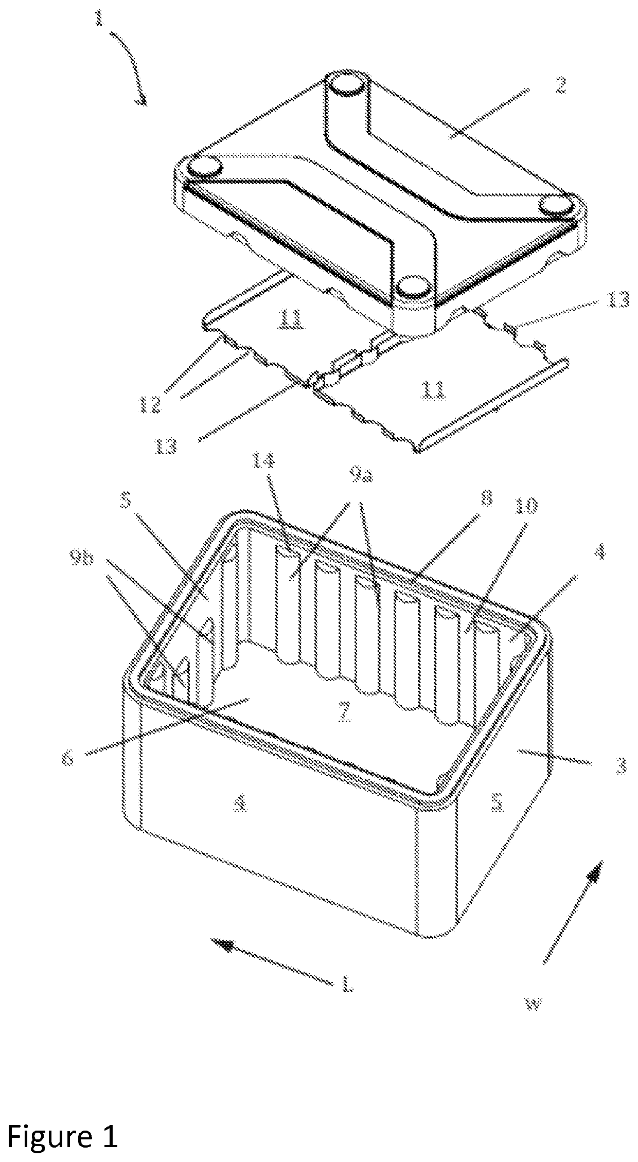
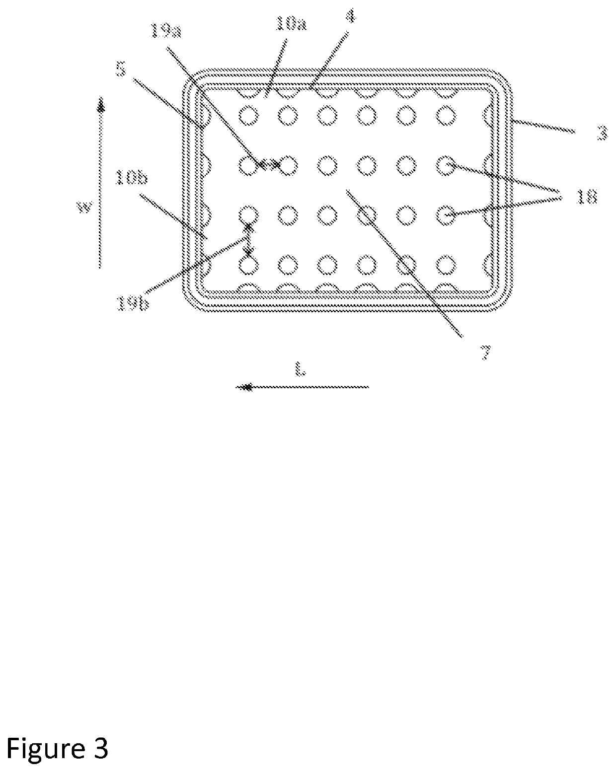
[0076]FIG. 1 shows a thermally insulated transport box. The thermally insulated transport box 1 comprises a cover 2 and a box body 3. The box body 3 is closed with the cover 2. The box body 3 comprises side walls 4 in the lengthwise direction L, end walls 5 in the crosswise direction w, an opening 6 and a bottom wall 7. The upper edge of the box body 3 comprises a flange 8 surrounding the opening 6 and when the box body 3 is closed, the side walls of the cover 2 surround the flange 8.

[0077]The inner surfaces of the side walls of the box body 3 comprise half columns 9a projecting from the side wall 4. The inner surfaces of the end walls 5 comprise half columns 9b projecting from the end wall 5. The half columns 9a-b run vertically along the side walls 4 and along the end walls 5 and project inwards. Between two adjacent half columns 9a-b is a gap 10, which comprises a substantially flat wall part.

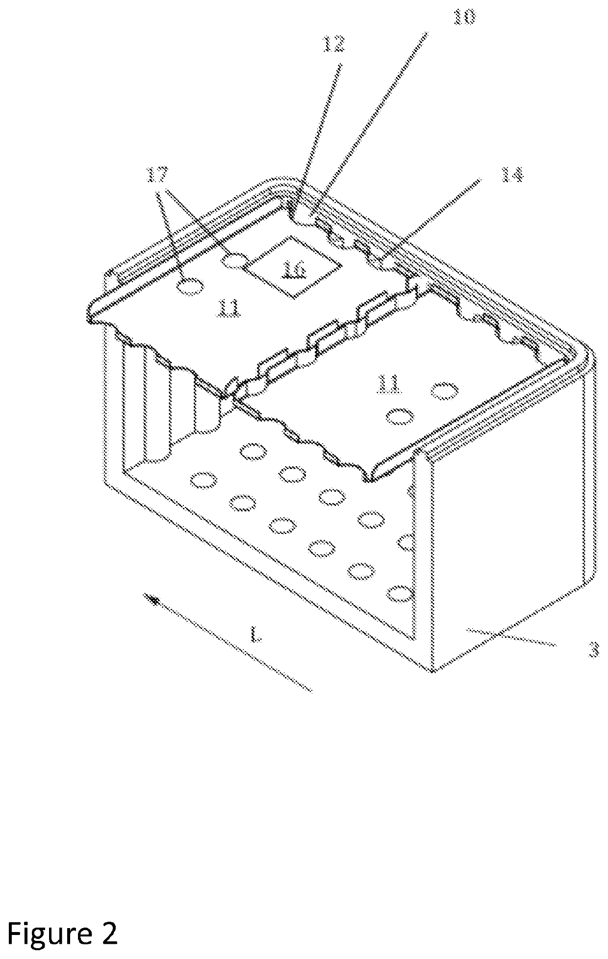
[0078]The box 1 comprises at least one separating partition 11 comprising notches 12 in ...


PUM


Abstract

The invention relates to a thermally insulated transport box and an arrangement in a thermally insulated transport box, wherein the box comprises a cover and a box body. The box body side walls, end walls, an opening and a bottom wall. The inner surfaces of the side walls comprise half columns projecting from the side wall, wherein the inner surfaces of the end walls further comprise half columns projecting from the end wall, and the half columns run vertically along the side walls and along the end walls. The box further comprises at least one partition wall comprising notches in its opposing edges, and as the partition wall is positioned to cover at least part of the opening the partition wall is supported by the half columns.

Description

FIELD OF THE INVENTION[0001]The present invention relates to a thermally insulated transport box and to an arrangement in a thermally insulated transport box, and particularly to a thermally insulated transport box, which is portable and can be used for transporting temperature sensitive goods.BACKGROUND OF THE INVENTION[0002]On certain occasions temperature sensitive goods such as drugs and foodstuffs need to be transported and temporary stored at containers where appropriate temperatures have to be maintained without electricity.[0003]An example is a transportation of vaccines to remote areas. Immunization programs have been using insulated containers as vaccine carriers for decades. Typically, the last-mile transport of vaccines is made by humans walking or on motorbikes carrying the insulated container. The temperature range at which decay of most pharmaceutical compounds is the lowest is typically +2° C. . . . +8° C. However, because many vaccines are freeze sensitive it is als...

Claims


Application Information

Patent Timeline
Patent Type & Authority Applications(United States)
IPC IPC(8): B65D81/38B65D25/04A61J1/16B65D81/18
CPCB65D81/18B65D81/3813B65D25/04A61J1/165F25D3/08F25D2303/08222F25D2303/0843F25D2303/0844F25D2303/0845F25D23/069F25D2303/08221
Inventor AMINOFF, MIKKONAUKKARINEN, JANNELINDEBERG, ERKKIPUUSTINEN, JUKKA
Owner 2COOL FINLAND OY
Why Eureka
Try Eureka