Module and device for emitting electromagnetic waves
Pending Publication Date: 2020-08-13
REMEDEE LABS
9 Cites 2 Cited by
AI-Extracted Technical Summary
Problems solved by technology
However, regular intake of such analgesic active ingredients can cause undesirable side effects (for example: nausea, drowsiness, heartburn).
However, the use of this technique requires a bulky device composed of electrodes to be placed on the patient's body and connected to an electric generator.
In addition, it produces a tingling feeling which can be experienced as unpleasant by the patient.
Although ...
Method used
[0109]The frequency oscillator 32 is placed in a cavity (not shown) within the housing 37 which allows not to disturb the generated frequency. The size of this BGA housing 37 is, in this case, 2.2×2.2×0.9 millimeters. The connection to the antennas 28 is made by means of “balls”43. This set of components makes it possible to minimize the losses of electromagnetic waves. It is the antenna 28 which transmits electromagnetic waves to the skin of the patient 1. Needless to say, the arrangement of the ASICs, control interface and antennas within the transmission module may be different.
[0119]Alternatively, by placing the ASIC/four antenna pairs separately at different locations on the patient's skin, this 2.5 cm2 surface is i...
Benefits of technology
[0013]Therefore, an object of the invention is to treat pain effectively by means of electromagnetic waves, and to make the devices provided for this purpose accessible and easily usable ...
Abstract
The invention concerns a portable device for transmitting electromagnetic waves. It is capable, when arranged at a surface, of transmitting waves having a power flux density of at least 0.5 milliwatts per square centimeter of surface area and a frequency value of between 3 and 120 gigahertz. The device is, moreover, capable of simultaneously exposing at least 2.5 square centimeters of the surface to the waves.
Application Domain
ElectrotherapyDiagnostics +2
Technology Topic
PhysicsEngineering +3
Image
Examples
- Experimental program(2)
Example
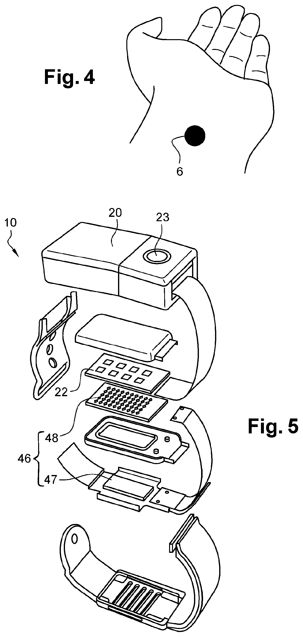
[0098]FIG. 4 illustrates a first embodiment of such a device;
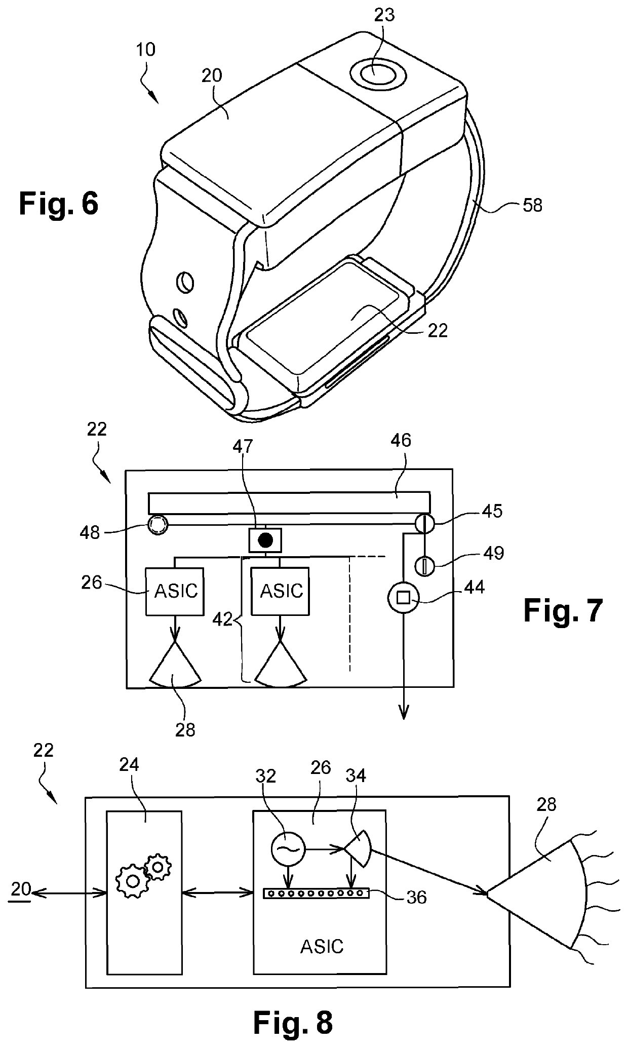
[0099]FIGS. 7 to 15 are diagrams of the components of a wave transmission module according to a first embodiment;
[0100]FIGS. 16 and 17 are illustrations of such a module respectively without and with heat sink;
[0101]FIG. 18 is an illustration of a radiation of the module of FIGS. 14 and 15;
[0102]FIGS. 19 and 20 are illustrations of use according to the second and third embodiments of the invention; and
[0103]FIGS. 21 to 29 illustrate components of a module according to other embodiments of the invention.
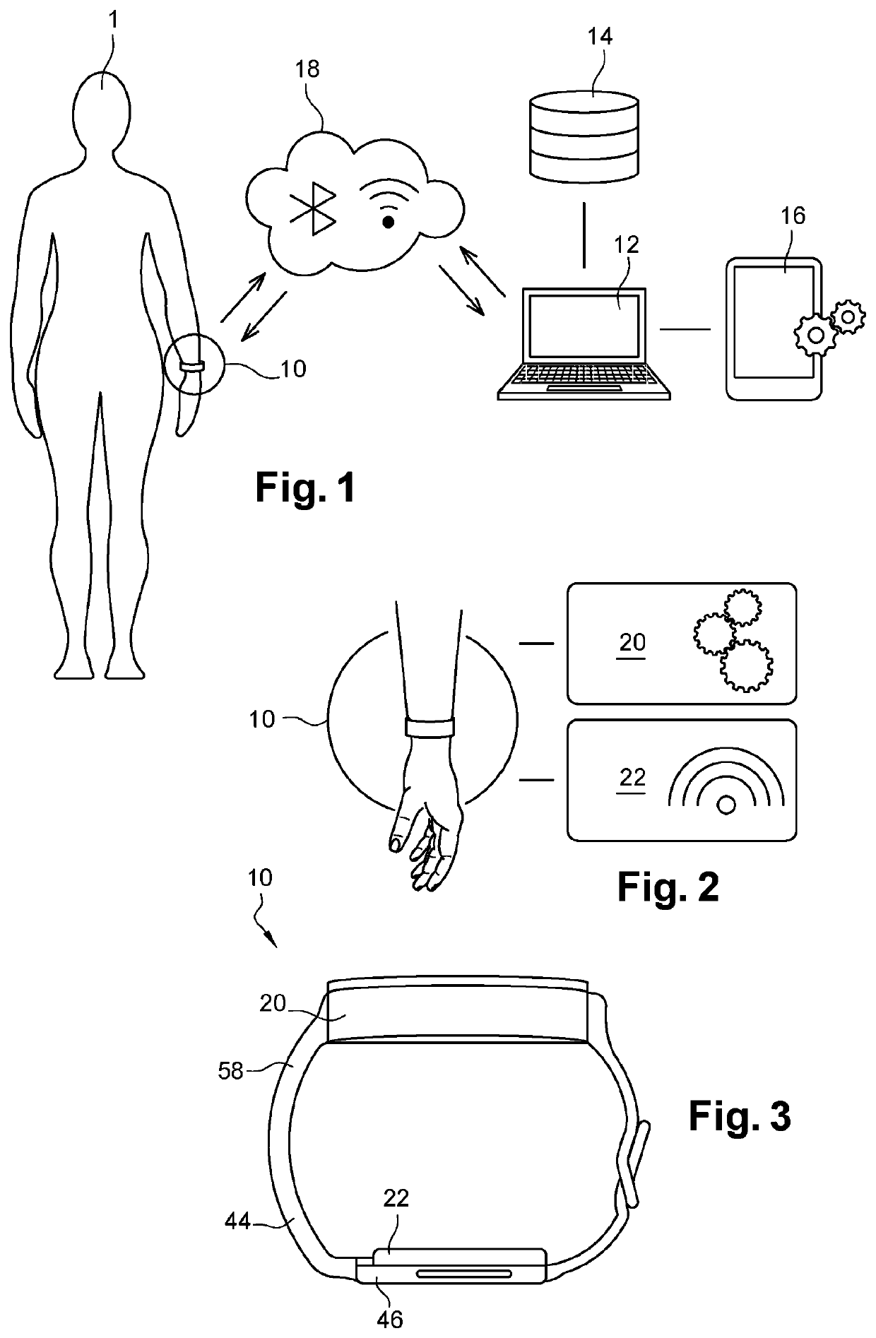
[0104]FIG. 1 illustrates the general framework of the invention. Patient 1 has chronic pain. He wears a device 10, according to a first embodiment and a first implementation of the invention, which treats the pain by transmitting electromagnetic millimeter waves to the skin of patient 1's wrist. In this case, this device 10 is in the general form of a wristwatch, and is affixed around the wrist in the same way as a watch. The device 10 comprises a control module 20 and a wave transmission module 22 illustrated schematically in FIG. 2 and in more detail in FIGS. 3, 5 and 6. The device 10 being in the general form of a watch, it may be a watch in which the modules 20 and 22 are integrated. Conversely, the functions of a watch may be integrated into device 10.
[0105]The control module 20 controls the transmission module 22. The control module 20 is activated by the patient, but it may also be programmed by the patient or another user, on the device 10 directly with the button 23 or via a terminal such as the computer 12. The button 23 is provided with light-emitting diodes which can be activated to indicate an event to the patient, for example a lack of battery or the operation of a particular program in progress. The control module 20 is present in the upper part of the device 10 while the millimeter wave transmission module 22 is located in the lower part and therefore intended to be in contact with the skin of the lower part of the wrist.
[0106]The wave transmission module 22, integrated into the device 10, will now be described in detail. It is a transmission module according to a first embodiment. This type of module, as well as its other embodiments, may be integrated into any type of device aimed at transmitting waves, and not only into the device 10 in the form of a wristwatch. Its applications are not limited to the treatment of pain.
[0107]This transmission module 22, schematically illustrated in FIG. 7, presents several circuit-antenna pairs 42, a heat sink 46, a skin sensor 44, a power input 45, a digital control unit 47, a reference clock 48, and a temperature sensor 49.
[0108]Each circuit-antenna pair 42, one of which being diagrammatically illustrated in FIG. 8, presents a control interface 24 in connection with the control module 20, an ASIC (“application-specific integrated circuit”) 26 and an antenna 28. The interface 24 may be located within the control module 20. The ASIC 26, as illustrated in FIG. 8, comprises an oscillator 32, a power amplifier 34 and a digital part 36 for setting and controlling the component. Illustrated in more detail in FIG. 9, it also includes a frequency divider 31, a communication bus 35, a “pulse-width modulation” (PWM) control unit 37 and a frequency comparator 38. The oscillator 32 allows the ASIC operating frequency to be generated. The amplifier amplifies this signal so that the desired power is available at the component output. This power is adjustable between 0 and 20 mW. It may conceivably go up to 60 mW without any difficulty. The frequency comparator and the divider make it possible to check the operating frequency. The power management circuit makes it possible to supply all of the component's functions correctly. Finally, the “PWM” control unit makes it possible to transmit the HF output signal continuously or discontinuously. The framework of the ASIC is shown in FIG. 12. This ASIC 26 is manufactured using complementary metal-oxide semiconductor (CMOS) technology, which is known to the person skilled in the art and will not therefore be described in detail. More specifically, the transistors are of the “CMOS 65 nanometer” type. Alternatively, they could have been developed in silicon-germanium (SiGe) or even in gallium arsenide (GaAs). On the other hand, technologies of the “Gunn diode” type do not allow to achieve the desired minimum size and cost. Thus, the ASIC 26 includes a silicon integrated circuit 33 housed in a ball grid array (BGA)-type housing 37, a type of housing well known to the person skilled in the art, tailor-made for the ASIC 26, the housing also comprising balls (called “bumps”) 35. As illustrated in FIG. 13, the circuit 33 is welded on two layers 71 and 72 of “HF” substrate 39 made of PTFE (Polytetrafluoroethylene) R03003, for example, manufactured by Rogers, with an arrangement known as a “flip chip”, which makes it possible to minimize the losses of electromagnetic radiation at high frequency. An alternative to R03003 could be MT77 (for example, from Isola) impregnating woven glass fibers, or even RF301 (from Taconic), or any other material offering the same technical advantages as those mentioned. The two layers 71 and 72 are separated by a layer 73 of RO4450F as well as by copper layers 74, 75, 76 and 77. In addition, vias 81, 82, 83 and 84 make the connections between the different layers of the substrate. Understandably, the types of layers and their number could be different.
[0109]The frequency oscillator 32 is placed in a cavity (not shown) within the housing 37 which allows not to disturb the generated frequency. The size of this BGA housing 37 is, in this case, 2.2×2.2×0.9 millimeters. The connection to the antennas 28 is made by means of “balls”43. This set of components makes it possible to minimize the losses of electromagnetic waves. It is the antenna 28 which transmits electromagnetic waves to the skin of the patient 1. Needless to say, the arrangement of the ASICs, control interface and antennas within the transmission module may be different.
[0110]The terminal connection 41 between an ASIC 26 and its antenna 28 is visible in FIG. 14. Thus, a coaxial connection 41 ensures the transmission of the wave between the power amplifier 34 and the antenna 28. Antenna means generally any form of radiating element, provided that it is flat. This type of radiating element can be called a “patch”.
[0111]As shown in FIG. 15, the ASIC 26 and the antenna 28 are arranged on either side of the substrate 39.
[0112]The set of antennas 28 forms an array of antennas, illustrated in FIG. 10. Rectangular-shaped here, this array of antennas, intended to be placed against the skin of patient 1 or at a short distance from it, is approximately 2.5 centimeters long by about 1 centimeter wide. It is provided, in this case, with 27 radiating elements 28 operating in near field, on the basis of three rows of nine antennas, aligned vertically and horizontally with respect to each other. These quantities and these arrangements are not limiting and others may be considered. The other elements of FIG. 7 and FIG. 9, in particular the temperature sensor 49, the skin sensor 44, the clock 48 and the power module 45 are arranged around this array of antennas, also called active area, as illustrated in FIG. 22 in a slightly different embodiment described below. The assembly formed by these elements and the active area located inside measures 37×20 mm and forms the transmission module 22, which may be integrated into a device such as a bracelet.
[0113]This arrangement allows the active area to transmit waves homogeneously over 2.5 square centimeters of skin. “Homogeneous” means that the intensity of the waves arriving on the skin must not present a deviation greater than about 30% between its maximum value at one point and its minimum value at another. FIG. 18 shows the radiation emitted by the device on the patient's skin in a normal operating mode. The black forms correspond to radiation between 5 and 15 mW/cm2, the white forms to radiation below 5 mW/cm2. It is observed that 75% of the surface is irradiated by waves of density between 5 and 15 mW/cm2. In general, the power density can be greater than 35 mW/cm2, but the device is designed so that the power range used is of the order of 5 to 35 mW/cm2 in normal operation, in particular for 30 minutes of continuous wave transmission. This operating mode is indeed the most usual, as will be described below.
[0114]FIG. 11 illustrates an application of the module 22 for transmitting waves towards the skin 60 of patient 1. A distance of 3 millimeters separates the module from the skin of the patient in this case. Although the objective is to affix the device to the skin, it may happen that a slight space is created between the skin and the device. Furthermore, for more comfort and for reasons of biocompatibility, a silicone layer 52 separates the antennas from the skin, so that the skin does not have to directly support the antennas. Alternatively, it may be another material transparent to millimeter waves, such as polycarbonate. This layer 52 of silicone may measure from 1 to 2 millimeters, the design of the antennas allowing the layer 52 to have only little or no interference with the waves emitted.
[0115]Overall, this wave transmission module 22, which can be called millimeter module (the waves being said to be “millimeter” in view of their frequency) or millimeter card, measures 37 millimeters in length, 20 millimeters in width and is 3 millimeters thick in this embodiment. Therefore, the volume of the millimeter module is 2.96 cubic centimeters. As shown in FIG. 16, it is therefore less than four, and even less than three cubic centimeters, which makes it possible to insert it into light low-volume devices, such as the device 10 in the form of a wristwatch. Having this volume and the described arrangement presenting 27 antennas, the ASICs 26 developed, coupled to the antennas 28, allow the millimeter module to transmit waves of frequency between 3 and 300 gigahertz, preferably between 30 and 120 gigahertz. The preferred frequency is 61.25 GHz+/−250 MHz. In all cases, the power flux density is at least 0.5 milliwatts per square centimeter, and the waves are transmitted simultaneously on a skin surface of 2.5 square centimeters. However, a millimeter wave treatment is effective at a power density starting from 0.5 milliwatts per square centimeter, preferably on a surface of at least 1 square centimeter. Therefore, the disclosed module makes it possible to carry out the treatment because it is easily integrated into any device due to its small volume.
[0116]It is understood that the ASICs, the antennas, as well as the whole of the millimeter module 22, may have different volumes, numbers and arrangements.
Example
[0117]Thus, in a second embodiment, illustrated in FIGS. 21 to 23, the module's performances are identical. The difference is that an ASIC is coupled to four antennas on a surface of 10×6.25 mm Therefore, this ASIC/antenna pair covers a skin surface of 0.625 cm2, on a PCB substrate 1 mm thick. Repeated four times side by side in the millimeter module illustrated in FIGS. 21 to 23, the four ASICs are each placed in a different “BGA” housing, whose size is 2.2 mm×2.2 mm×1 mm. The module, which then includes two rows of eight antennas and 4 ASICs (4 housings), thus makes it possible to continuously irradiate 2.5 cm2 of skin surface.
[0118]An antenna array 91 according to this embodiment is illustrated in FIG. 21. Array 91, said to be a “resonant cavity” array, comprises four layers. The layer 92 allows the routing of digital and power signals. The second layer 93 represents the access lines to the antennas. The third layer 94 represents the coupling lines. Lastly, the fourth layer 95 is that from which the waves will be transmitted. This antenna array is also implemented in the previous embodiment, the only difference being the number of antennas and ASICs, and, therefore, the arrangement of these elements.
[0119]Alternatively, by placing the ASIC/four antenna pairs separately at different locations on the patient's skin, this 2.5 cm2 surface is irradiated, but in several distinct areas. Likewise, each of these pairs may be used independently in order to ensure greater comfort or to be integrated into applications which require a smaller surface, or a lower power.
[0120]The skin sensor 44 of the embodiments described uses a capacitive type measurement making it possible to determine that the patient's skin is positioned near the millimeter module 22. Its structure is known to the person skilled in the art and is not limited to a capacitive measurement, any miniaturizable skin sensor being admissible. Connected to the control interface 24 and/or to the control module 20, the skin sensor 44 determines the presence or absence of human or animal skin. It is also able to determine the distance between the skin and the millimeter module. At 3 millimeters or less, wave transmission is allowed. Otherwise, the control module 20 can prevent the wave transmission. The objective here is to prevent inefficient wave transmission in order, on the one hand, to control the direction of the waves transmitted, and, on the other hand, to save energy. In the first embodiment, the skin sensor 44 is located outside the module, on a side of the device 10.
[0121]The millimeter module 22 may further comprise a rechargeable battery. Preferably, the device assembly comprising the module 22, such as the device 10, has a battery supplying both the control module 20 and the wave transmission module 22. This battery can be recharged conventionally from the mains or any other way. It is, naturally, interesting that its autonomy is several hours, even several days, so that the patient's portable device aimed at treating his pain is more convenient to use.
[0122]Some of the module components may needless to say, be placed outside thereof to better interact with the device comprising the module, such as the battery.
[0123]Apart from the control module 20, the millimeter module 22 and the skin sensor 44, the device 10 includes other components which will be described now.
[0124]The band 58 of FIG. 3 is flexible and aims to adapt to the shape and size of the wrist, as would a conventional watch strap.
[0125]The device 10 also includes a dissipator 46, shown in FIG. 5, which may be considered as part of the millimeter module 22. In the present case, it is located outside this module, and comprises a flexible band 47 and a thermal buffer 48, the two components being inserted within the strap of the device 10. The band 47 is associated with graphite and rubber. The rubber allows the band to be flexible and therefore adaptable to the strap. The graphite is light and has good thermal conductivity. The band 47 may be made of another elastomeric material than rubber. It may also be made of a completely different material, which needs to be flexible in order to adapt to the shape of the device. The buffer 48 includes a phase-change material. Thus, during heat release due to the operation of the device, the phase-change material absorbs part of the calories generated and allows to maintain the overall temperature. The dissipator is arranged with the device in order to maintain the temperature of the surrounding area of the body below 43° C. for a continuous operation of the device of approximately 30 minutes. This temperature of 43° C. corresponds to maximum temperature standards set by certain authorities, and that is why the device is designed to comply with these standards. It could thus be designed differently if the maximum authorized temperature were higher. The temperature is monitored by the temperature sensor of the millimeter module 22.
[0126]The device 10 further includes a unit (not shown) for determining the impedance of the skin. This unit may be part of the millimeter module 22.
[0127]The frequency of the waves transmitted by the device 10 via the module 22 may be between 3 and 300 gigahertz for an effective treatment. However, the frequency of the device disclosed preferably varies between 30 and 120 gigahertz, with a preferred frequency around 60 gigahertz, in particular around 61.25 gigahertz.
[0128]Each component's dielectric properties, such as its permittivity, conductivity and loss tangent, had to be taken into account for the design of the module 22 and the device 10. Simulations and tests outside the nominal operating range of the 65 nm CMOS type ASIC transistors were carried out, and do not call into question the lifetime of the components with regard to the implementation of the millimeter wave treatment which will be disclosed below.
[0129]The implementation of pain treatment in the patient will now be disclosed.
[0130]This treatment aims to transmit waves towards an area of the patient's skin. The transmission generally lasts 30 minutes, at the rate of one transmission to two per day. The frequency, preferably between 30 and 120 gigahertz, is predetermined. It may possibly vary during a transmission, as does the power flux density which generally varies between 5 and 35 mW/cm2, but can be lower or higher than this range. Needless to say, any other type of treatment is possible, in particular with longer and/or more frequent transmissions.
[0131]In a first embodiment, the waves are transmitted by the module 22, integrated into the device 10 in the form of a wristwatch, towards the wrist, a highly innervated area, and may be placed on the acupuncture point Pericardium 6 referenced in FIG. 4, which is a known acupuncture point. It has indeed been shown that the transmission of waves to acupuncture points was particularly effective in the treatment of pain. In addition, very good results are also achieved for particularly innervated areas. Indeed, the stimulation of the nerve endings located under the skin induces a set of physiological actions called “systemic response”, actions which in turn induce the synthesis of endogenous opioids (including the enkephalin) themselves responsible for decrease in pain. Thus, the more the wave transmission takes place in an area with a high density of nerve endings, the more the treatment is likely to be effective. Point Pericardium 6 is an acupuncture point at the same time located in an area rich in nerve endings. Therefore, a device transmitting waves towards this area is of utmost interest.
[0132]Furthermore, other potential benefits, described in the literature associated with this increase in the synthesis of opioids, are known, such as a decrease in heart rate and stress, improved sleep, or even a euphoric effect. Therefore, such benefits can be drawn from the device 10.
[0133]The frequency, the duration, and the power of the waves can be parameterized by means of the module 20 of the device 10. As illustrated in FIG. 1, it can be programmed in advance by means of a terminal, for example a computer 12, which can communicate with it by any telecommunication network, such as a Bluetooth or Wi-Fi type link 18. The computer 12 includes a database 14 on which is recorded a program 16 implementing the process or processes having a link with the invention, as well as various data allowing the implementation of the invention, in particular data entered by the patient 1 and data obtained by the device 10.
[0134]In addition, by determining the impedance of the skin using the impedance detection unit, the latter transfers to the control module 20 a characteristic data of the patient's skin. Parameters of the waves transmitted by the module 22 can then be modified automatically via the control unit 20, thanks to the program 16, or manually by the patient or another user. Thus, the device 10 adapts to the patient's skin. In other words, the electromagnetic field created is controlled by the characteristics of the skin. Il can also be modified based on the distance measured between the skin and the device, via the skin detector 44. The device may include other units determining and processing other data obtained directly from the patient, which can serve to adapt the parameters of the transmitted waves such as power, frequency and duration of transmission.
[0135]Other embodiments of the transmission module are illustrated in FIGS. 24 to 29. They differ from the previous embodiments by their number of ASICs and antennas. Thus, the module in FIG. 24 comprises 8 ASICs. In addition, one or more radiating elements may correspond to an ASIC. Thus, the module 320 comprises 4 ASICs for 8 radiating elements, at the rate of 2 radiating elements for 1 ASIC. Finally, module 420 comprises 6 ASICs and 6 radiating elements.
[0136]Furthermore, the transmission module may also be integrated into another device, for example intended to be worn by the patient in another part of the body. Thus, FIG. 19 illustrates a device 100 according to a second embodiment comprising the control and transmission modules placed on the ankle, while FIG. 20 illustrates such a device 1000 according to a third embodiment placed on the calf. Therefore, in these second and third embodiments, the waves are transmitted to other areas of the patient's body by means of devices which differ from the device 10 essentially to adapt to the targeted area of skin. In all cases, the miniaturization of the modules allows the device to be light and not bulky, so that it is easy to wear and not excessively burdensome.
[0137]Modifications are possible within this transmission module. For example, the structure of the antenna array may be different and present a “micro ribbon” type supply line or a coaxial probe. The antennas may be long slot antennas.
[0138]The control module may also be integrated into the electromagnetic transmission module.
[0139]Therefore, several embodiments and implementation modes were presented, which all allow the transmission of electromagnetic waves having a power surface density of at least 0.5 milliwatts per square centimeter of surface, a frequency value between 3 and 120 gigahertz, and simultaneously on a surface of at least 2.5 square centimeters, whether continuous or spread over several separate parts of the surface.
[0140]Aside from any pain treatment, the wave transmission module, possibly in conjunction with the control module, may be interesting for transmitting waves for other purposes, for example, to improve sleep, since it is particularly miniaturized, and therefore light. Consequently, it can be integrated into any device when it is necessary to send millimeter waves to a surface or in any direction.
[0141]Furthermore, the transmission module, or the control module, and/or the device integrating these modules, may be controlled remotely, from a terminal such as a computer, but also from a mobile terminal. For example, a mobile application comprising a pain treatment program may be saved on the mobile terminal, so that the patient programs his treatment himself, for example the power, the frequency, the duration and the time of wave transmission, or his doctor or any medical assistant programs these parameters remotely. In this case, the terminal comprises software presenting one or more interfaces allowing the user of the terminal to configure the device. The program allowing the implementation of the invention may be downloaded via a telecommunication network.
[0142]It may be added that the transmission module, as well as the device comprising it, may also be used in order to reduce the patient's stress or even bringing a feeling of well-being.
[0143]As a corollary, one can envisage the use of the transmission of electromagnetic waves within the framework of a program of improvement of a problem to be solved as perceived by the patient. The program may consist of the commitment on a series of supervised uses of the treatment with evolution of the exposure parameters (frequency, power, etc.). A discovery session, followed by a session adapted to the patient's feeling and the power of the effect perceived could be envisioned. The following sessions could also be adapted based on the measurement of said effect if sensors allow to measure it. Lastly, the treatment session could be triggered by the user through a program, or automatically if sensors allow to measure the need thereof.
[0144]Naturally, several modifications may be made to the invention without departing from the scope thereof.
PUM


Description & Claims & Application Information
We can also present the details of the Description, Claims and Application information to help users get a comprehensive understanding of the technical details of the patent, such as background art, summary of invention, brief description of drawings, description of embodiments, and other original content. On the other hand, users can also determine the specific scope of protection of the technology through the list of claims; as well as understand the changes in the life cycle of the technology with the presentation of the patent timeline. Login to view more.
Similar technology patents
Lockable attachment and styptic device including same
InactiveUS20130131721A1easily manufacturableeasily usable
Owner:BENRIKAL SERVICES
Sample holder unit for single-crystal x-ray structure analysis apparatus
PendingUS20210396690A1easily usableeasily carry out
Owner:RIGAKU CORP
Methods and systems for accessing financial prospectus data
InactiveUS7349873B2easily usablefacilitate provision
Owner:CFPH LLC
Classification and recommendation of technical efficacy words
- easily usable
Lockable attachment and styptic device including same
InactiveUS20130131721A1easily manufacturableeasily usable
Owner:BENRIKAL SERVICES
Methods and systems for accessing financial prospectus data
InactiveUS7349873B2easily usablefacilitate provision
Owner:CFPH LLC
Sample holder unit for single-crystal x-ray structure analysis apparatus
PendingUS20210396690A1easily usableeasily carry out
Owner:RIGAKU CORP