
Tourniquet Buckle Assembly

a technology of buckles and tourniquets, applied in the field of tourniquets, can solve the problems of difficult self-application of tourniquets, uncontrolled hemorrhage from trauma remains a major cause of death, and the difficulty of etc., to achieve the effect of convenient one-handed application of tourniquets

Active Publication Date: 2020-09-17
TACTICAL MEDICAL SOULUTION INC
View PDF5 Cites 1 Cited by
  • Summary
  • Abstract
  • Description
  • Claims
  • Application Information

AI Technical Summary

Benefits of technology

Enables rapid, one-handed application and release of the tourniquet, reducing time and effort, and allowing for targeted tightening, thereby improving hemorrhage control in emergency situations by minimizing delays and maintaining secure blood flow occlusion.

Problems solved by technology

Uncontrolled hemorrhage from trauma remains a major cause of death, both on the battlefield and in civilian situations.
Untreated, extreme bleeding as in the case of arterial bleeding can cause hypovolemic shock within just minutes.
Tourniquet self-application is especially challenging when the victim is constrained to using only one hand.
A drawback to some of these known tourniquets is, under certain circumstances, they do not facilitate speedy deployment to trapped limbs.
In addition, that process delays tourniquet application where even a few seconds of delay can cause fatal blood loss.
Another shortcoming of some known tourniquets designed for one-handed application is that they are sometimes difficult to cinch even when the strap is engaged with the buckle requiring several tugs on the strap and sometimes aid of a second hand.
Still further, at least some existing tourniquets delay one-handed release after use.
However, rapid incremental release of a tourniquet can be life-saving when trained tourniquet users must adjust the position and / or location of the tourniquet or when next-step trauma management is available and necessary.
Such friction prevents the inadvertent release of the buckle but disadvantageously slows down the rapid release of the buckle when needed.
Additionally, friction between tourniquet buckle components may cause wear with repeated use.
Known tourniquets also restrict the rotational capability of buckle components once the buckle is engaged.

Method used


Image

  • Tourniquet Buckle Assembly
  • Tourniquet Buckle Assembly
  • Tourniquet Buckle Assembly

Examples


example

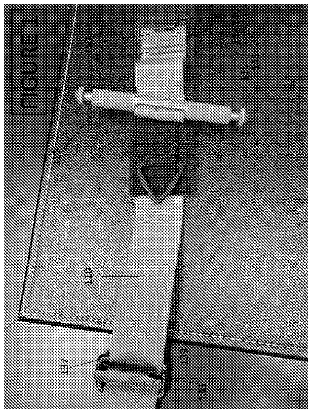
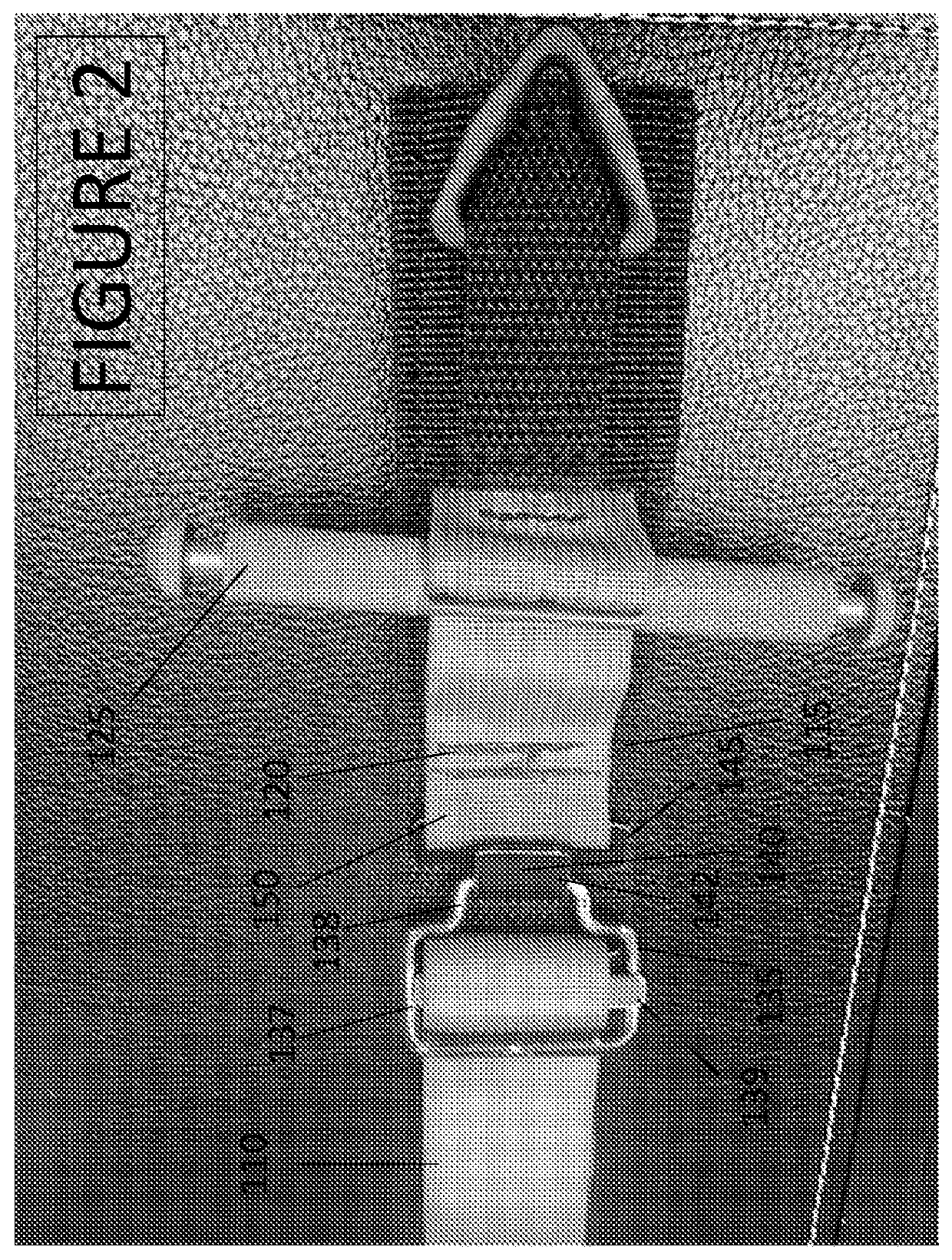
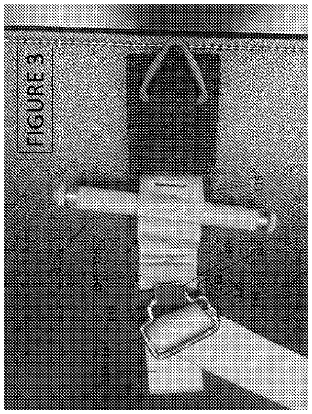
[0040]A tourniquet of the type shown in FIGS. 1-9 has a buckle 135 and a buckle connector 140 made from metal. In this example, the buckle 135 has a cylindrical diameter D1 of approximately 0.187″. The buckle 135 has a step member 138 and a frame member 137. The frame member 137 comprises three sides of a rounded rectangle with a base length 137C measuring approximately 1.5″ excluding the rounded corners and extended length S including the abutting rounded corners and measuring approximately 2.0″. Sides 137A and 137B each measure approximately 0.937″ including one rounded corner and have a truncated width T excluding rounded corners that measures approximately 0.688″. Step member 138 has a total length U about equal to the frame extended base length S or approximately 2.0″. Raised edge 138A is centered in the buckle frame such that the center of raised edge 138A is approximately 0.750″ or about halfway in from frame base 137C. The raised stepped edge 138A has a length of about 0.760...


PUM


Abstract

The present invention relates generally to first aid articles and more specifically tourniquets suitable for one handed application. One embodiment of the invention is directed to a tourniquet having a base defining first and second ends. A constricting band is attached to and extends from the first end of the base. A windlass handle is engaged with the constricting band. The constricting band is threaded through a self cinching stepped buckle. A buckle connector includes a hook member that engages the stepped buckle and is partly held in place through urging against a loop of the constriction band.

Description

[0001]This application claims the benefit of U.S. Provisional patent application Ser. No. 62 / 475,854 filed on Mar. 23, 2017, which is incorporated herein by reference in its entirety.I. FIELD OF THE INVENTION[0002]This invention relates to tourniquets suitable for one-handed application.II. BACKGROUND OF THE INVENTION[0003]Uncontrolled hemorrhage from trauma remains a major cause of death, both on the battlefield and in civilian situations. Untreated, extreme bleeding as in the case of arterial bleeding can cause hypovolemic shock within just minutes.[0004]Tourniquets are well-known devices used to stop blood loss from trauma. When properly deployed, they provide life-saving support in emergency situations when an injured victim is alone or cannot reach immediate medical attention. A standard tourniquet is a tightly tied or wound band applied around an injured limb in an attempt to increase pressure around the limb, above the injury and stop severe bleeding or uncontrolled hemorrhag...

Claims


Application Information

Patent Timeline
Patent Type & Authority Applications(United States)
IPC IPC(8): A44B11/12A44B11/28A44B11/00A61B17/132
CPCA44B11/28A44B11/006A44B11/125A61B17/1325A44B11/005A61B17/132A61B17/1327A44B11/18A61B2017/00477Y10T24/3404Y10T24/4081A44B11/06Y10T24/3405
Inventor JOHNSON, ROSS A.HESTER, RICHARD A.MORRIS, JOHN
Owner TACTICAL MEDICAL SOULUTION INC
Learn More