Optical interferometric-based physically unclonable function device

a technology of optical interferometry and function device, which is applied in the direction of optical elements, instruments, digital transmission, etc., can solve the problem of not being able to recreate the exact behavior of the device or process, and not being able to recreate the devi

Pending Publication Date: 2020-09-24
THE UNITED STATES OF AMERICA AS REPRESETNED BY THE SEC OF THE AIR FORCE
View PDF0 Cites 1 Cited by
  • Summary
  • Abstract
  • Description
  • Claims
  • Application Information

AI Technical Summary

Benefits of technology

[0019]Another object of the present invention is to exploit the uncontrollability inherent to the fabrication of evanescent and other types of waveguide couplers with the stability and scalability of integrated optical devices to create a programmable physically unclonable function with a larger number of unique settings.
[0020]Briefly stated, the present invention provides an apparatus for implementing a physically unclonable function via a network of interferometers implemented as a reconfigurable integrated optical circuit. The uncontrollable and non-repeating fabrication variation in the manufacturing processes of integrated optics, combined with the sensitivity of interferometers creates inherently unique devices that can be used as reprogrammable physically unclonable function.
[0027]The output of each MZI in the preferred embodiment is two waveguides, which split and are touted to two separate MZI in the next row. Thus the splitting of the first MZI affects the intensities of light entering the next two MZI. Light from a single input then propagates in a cone shape as it moves through the dives. The preferred embodiment is such that light from the first MZI can potential reach all other MZIs and all outputs. In this way no resources (i.e. MZIs or output waveguides) are wasted.

Problems solved by technology

A PUF is a device or process that is sufficiently delicate to the point that it is in practice impossible to recreate the exact behavior of the device or process.
Thus even the original creator of a PUF, in theory, could not recreate the device despite knowing all details of its original design, having identical materials and the same fabrication devices.
Notwithstanding the aforesaid availability of integrated optical PUFs, what has been lacking thus far is a programmable physically unclonable function with a scalable large number of unique settings.

Method used


Image

  • Optical interferometric-based physically unclonable function device
  • Optical interferometric-based physically unclonable function device

Examples


Embodiment Construction

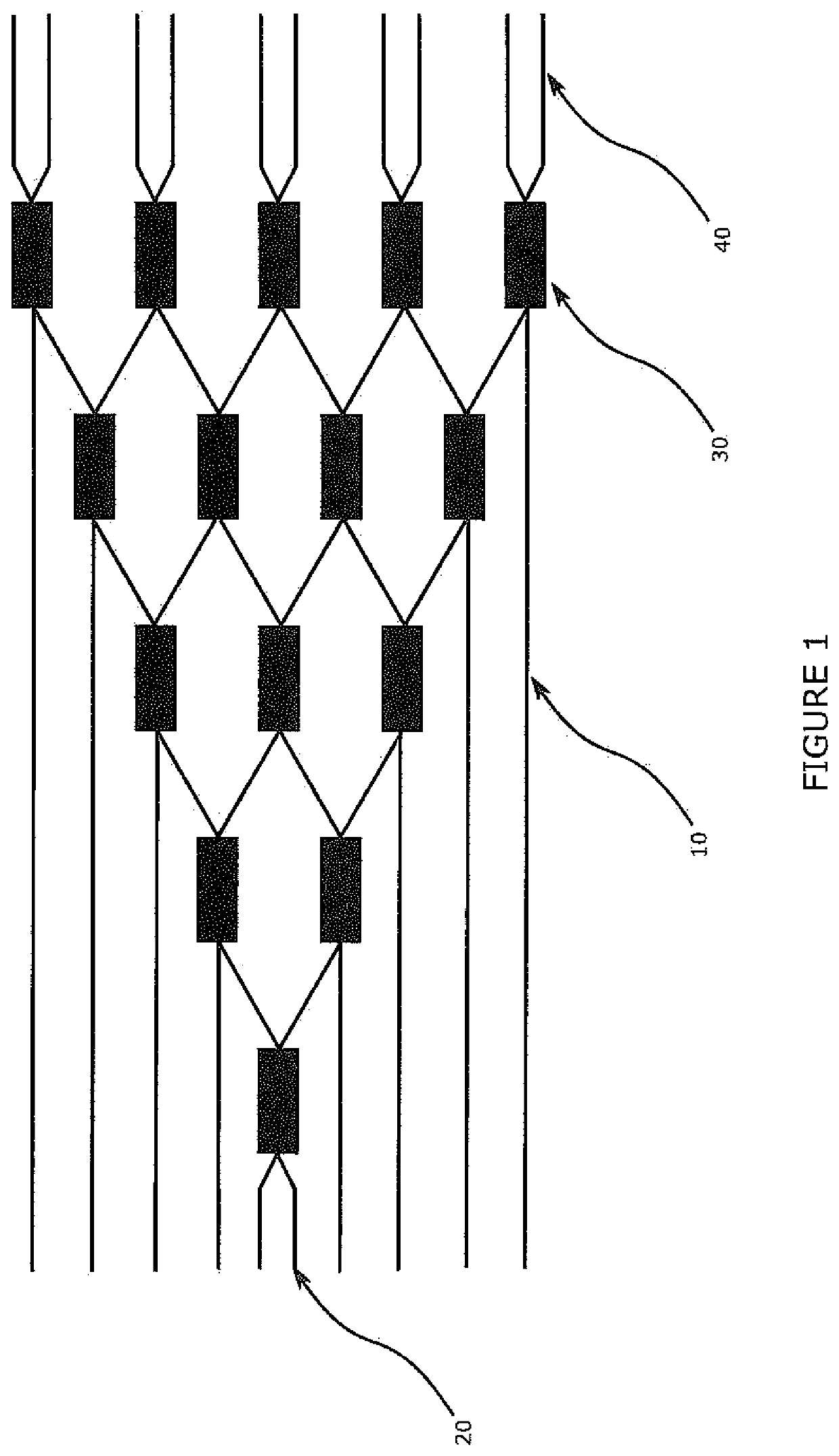
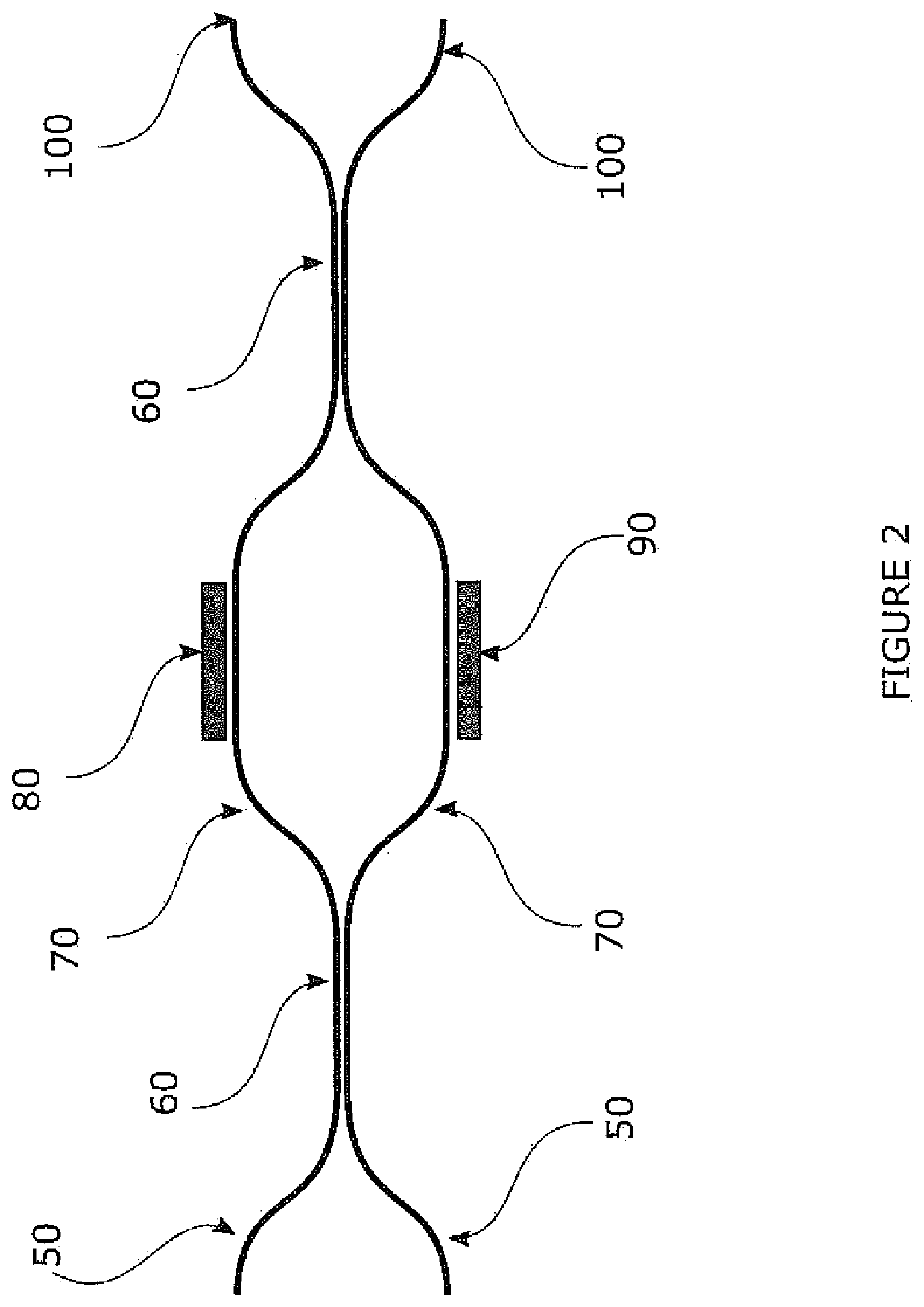
[0032]Referring to FIG. 1, the key components of the integrated optical PUF invention are shown. Light is assumed to propagate from left to right. This shows how the output of any given MZI 30 is split to two “nearest neighbor” MZIs in the next downstream column. Thus light from any one of several single device input waveguides 20 can spread to all possible MZIs 30 and device output waveguides 40. Waveguides such as 10 are depicted here as straight lines but may be contoured into any shape between the MZIs 30 without significant alteration of the invention. A main device input waveguide 20 is created such that light from this waveguide can reach all possible device output waveguides 40. FIG. 1 shows the manner of the interconnected nature of the MZIs 30. The MZI outputs (100, FIG. 2) of each individual 2×2 MZI 30 are split and feed into an MZI input (50, FIG. 2) of the next downstream column such that each MZI output (100, FIG. 2) goes to a downstream MZI 30 and into that downstream...


PUM


Abstract

An apparatus for implementing a physically unclonable function via a network of interferometers implemented as a reconfigurable integrated optical circuit. The uncontrollable and non repeating fabrication variation in the manufacturing processes of integrated optics, combined with the sensitivity of interferometers creates inherently unique devices that can be used as reprogrammable physically unclonable function.

Description

STATEMENT OF GOVERNMENT INTEREST[0001]The invention described herein may be manufactured and used by or for the Government for governmental purposes without the payment of any royalty thereon.BACKGROUND OF THE INVENTION[0002]This invention relates generally to the creation of a Physically Unclonable Function (PUF) device. A PUF is a device or process that is sufficiently delicate to the point that it is in practice impossible to recreate the exact behavior of the device or process. Such PUFs are currently in use as authentication tokens and cryptographic key seeds among other applications. A basic operating procedure for a PUF is as follows. First, the device is fabricated. Second, the device is characterized: meaning one user (the provider) applies a set of so-called challenges and records the unique response of the device. These are called Challenge and Response Pairs (CRPs). The nature of both the challenge and the response depends on the implementation method and underlying tech...

Claims


Application Information

Patent Timeline
Patent Type & Authority Applications(United States)
IPC IPC(8): H04L9/32
CPCH04L9/3278G02B6/2935
Inventor SMITH, A. MATTHEW
Owner THE UNITED STATES OF AMERICA AS REPRESETNED BY THE SEC OF THE AIR FORCE
Why Eureka
Try Eureka