
Storage device

a technology for storage devices and medical equipment, applied in applications, transportation and packaging, rigid containers, etc., can solve the problems of airborne contamination, unsatisfactory, and contamination derivation risk, and achieve the effect of preventing the disengagement of the tray compartmen

Active Publication Date: 2015-01-27
STERIS SOLUTIONS LTD
View PDF46 Cites 30 Cited by
  • Summary
  • Abstract
  • Description
  • Claims
  • Application Information

AI Technical Summary

Benefits of technology

[0020]As such, the present invention provides a single use storage device that allows valves and other components to be kept with a parent endoscope or other piece of medical equipment during storage, cleaning and sterilisation. In particular, the storage device may be used in hospitals for the storage of flexible medical endoscope valves together with their parent endoscope to ensure that they remain a unique set, before, during and after being processed in an automated reprocessing machine or by manual endoscope reprocessing.
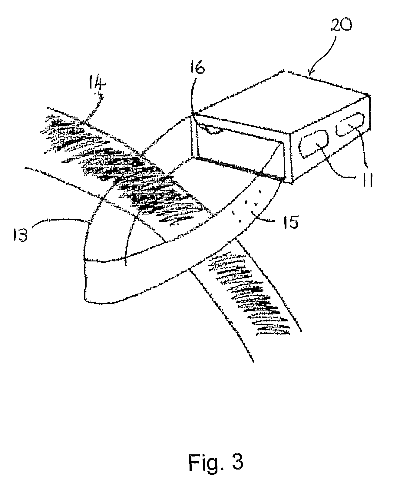
[0022]In preferred embodiments the connection portion includes one or more protrusions on a first surface. These are provided so that contact between the connection portion and the object to which the storage device is attached is minimised. For example, a strap connecting the container portion to the closure portion may include raised projections to minimise the contact of the strap with a parent endoscope umbilical (light-guide) cable around which the strap is looped.
[0025]Because the storage device is designed to be used only once, to minimise contamination of medical equipment for example, it is preferable to design the securing means so that disabling the securing means includes breaking a part of the securing means. To allow a user to easily break open the storage device, it is preferable if the closure portion includes a handle portion. The handle portion is arranged to enable a user to grip the handle to separate the closure portion from the container portion, thereby disabling or breaking the securing means.
[0029]In embodiments comprising a tray and a sleeve, preferably a first part of the securing means is provided on the tray compartment and a second part of the securing means is provided on the sleeve. In some embodiments it may be preferable if the first and second parts of the securing means comprise a plurality of semi-dome protrusions arranged such that when the tray compartment is engaged with the sleeve, flat surfaces of the protrusions interlock to prevent disengagement of the tray compartment from the sleeve.

Problems solved by technology

Moreover, the recent re-emergence of tuberculosis also presents a threat of airborne contamination in areas where endoscopes are being used and transported.
Existing methods of keeping endoscope valves with their parent endoscope vary between different countries and, notwithstanding the above guidance, these existing methods are generally considered unsatisfactory when based on such criteria as:the protection of the endoscope valves before, during and after the processing of the endoscope and valves, either manually or in an automated endoscope reprocessor (AER), against accidental damage or contamination;the protection of the staff, patients, and workplace against contamination and possible infection.
The risk of contamination deriving from a used and potentially unclean set of endoscope valves due to either the use of non-dedicated cages to store the valves which have a small mesh thus not allowing disinfection solution through, or the use of non-dedicated material bags to store the valves which soak up liquid and can themselves potentially become a biohazard; andthe protection of unused endoscopes against the potential for cross-contamination from contact with used endoscope valves carrying infectious matter.

Method used


Image

  • Storage device
  • Storage device
  • Storage device

Examples


Embodiment Construction

[0044]The storage device of the present invention is required to have a number of key properties. The device must be resistant to the cleaning and sterilisation fluids to which it will be exposed, and must be generally tough and durable. The storage device must protect its contents from damage and as such should be substantially rigid and robust. Finally, the device, while containing the valves or other components, must permit fluids to flow into and out of the device quickly and easily.

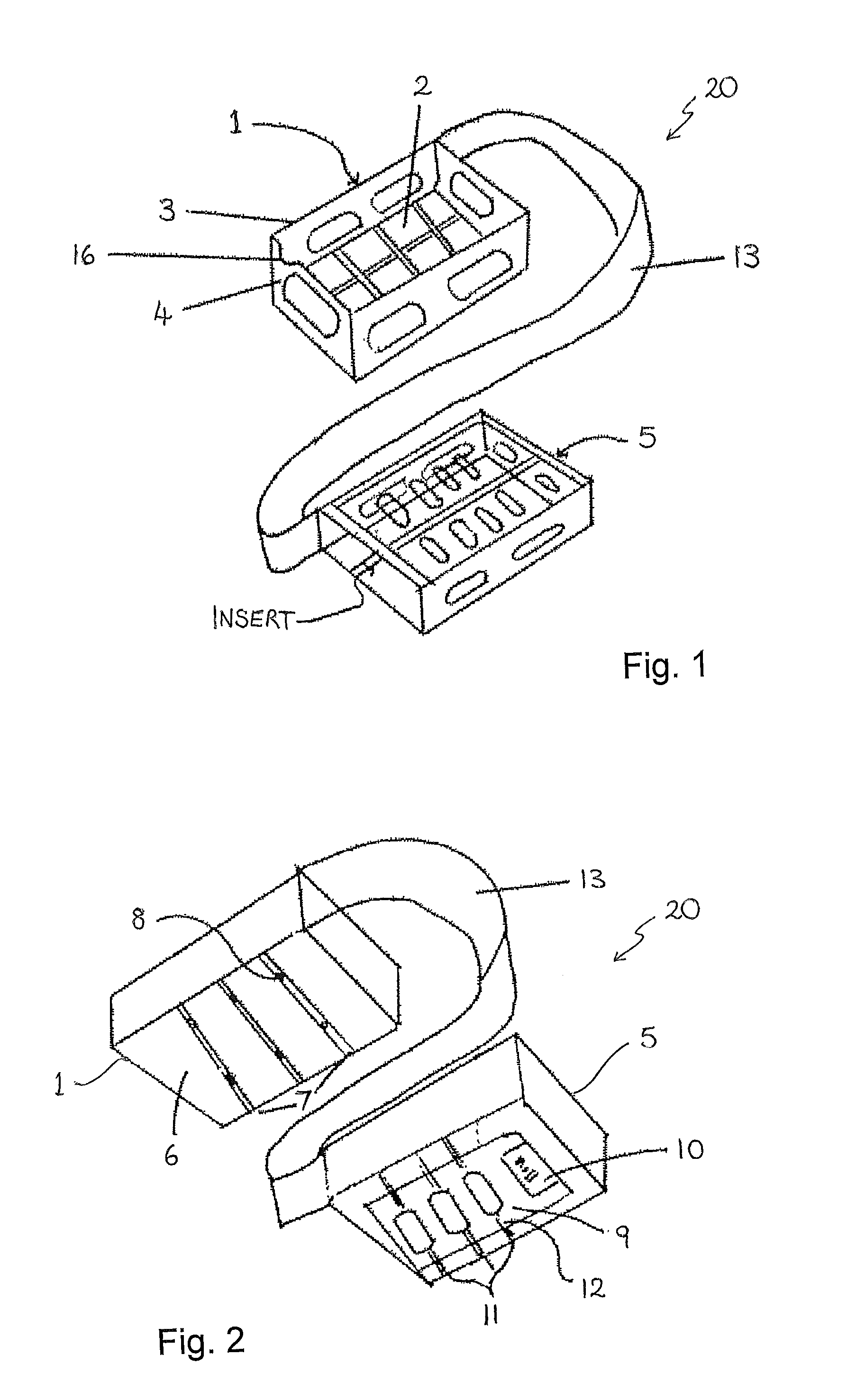
[0045]A first embodiment of the storage device 20 is illustrated in FIGS. 1 and 3. In this embodiment, the storage device 20 comprises a tray compartment 1 and a sleeve 5.

[0046]Referring first to FIG. 1, the tray compartment 1 is defined by a substantially rectangular base 2 and surrounding side walls 3 and end walls 4 upstanding therefrom on each side. Each wall 3, 4 is, preferably, curved at each end and at the bottom thereof, such that each side wall 3 merges imperceptibly with an adjacent end wal...


PUM

PropertyMeasurementUnit
lengthsaaaaaaaaaa
lengthsaaaaaaaaaa
lengthsaaaaaaaaaa

Abstract

The present invention relates to a device for storage of medical equipment. In particular, the present invention relates to a single-use storage device for components of a piece of medical equipment that retains the components with the piece of medical equipment. More particularly the storage device may be used to store endoscope valves, with the parent flexible endoscope. A single-use storage device for medical equipment comprises a container portion, for holding one or more pieces of medical equipment, a closure portion, designed to engage with the container portion to form an enclosure around said medical equipment, a plurality of apertures permitting fluid flow through the storage device, and securing means to secure the closure portion to the container portion, the securing means arranged such that once the closure portion has been secured to the container portion using the securing means the closure portion and container portion cannot be separated without permanently disabling the securing means.

Description

BACKGROUND[0001]a. Field of the Invention[0002]The present invention relates to a device for storage of medical equipment. In particular, the present invention relates to a single-use storage device for components of a piece of medical equipment that retains the components with the piece of medical equipment. More particularly the storage device may be used to store endoscope valves, with the parent flexible endoscope.[0003]b. Related Art[0004]Flexible medical endoscopes are used for the internal examination of various parts of the human or animal body. They are produced in diameters ranging from 0.02 to 0.6 inches (0.5 to 15 mm) and with lengths of 12 to 120 inches (300 to 3000 mm). The majority of endoscopes have internal channels, down which air, water or accessories may be directed so as to facilitate examinations, or to carry out surgical procedures. Each of these channels typically includes one or more valves used to restrict and / or direct the flow of fluids or air, or allow t...

Claims


Application Information

Patent Timeline
Patent Type & Authority Patents(United States)
IPC IPC(8): A61L2/00A61B19/02A61L2/26
CPCA61B19/026A61B19/0287A61L2/26A61B19/0256A61B2019/0202A61B2019/0211A61B2019/0245A61L2202/182A61L2202/24A61B2050/0058A61B2050/0089A61B2050/005A61B50/20A61B50/30A61B50/36A61B1/00131A61B1/0014A61B50/33
Inventor MARKOVITCH, DANIEL ANDREW
Owner STERIS SOLUTIONS LTD
Learn More