Fume treatment method and apparatus using ultraviolet light to degrade contaminants

a treatment method and technology of contaminants, applied in the field of exhaust systems, can solve the problems of not being able to choose the type of geometry, and achieve the effect of increasing the minimum dwell time and stable flow

Active Publication Date: 2006-10-05
HALTON GROUP LTD
View PDF21 Cites 66 Cited by
  • Summary
  • Abstract
  • Description
  • Claims
  • Application Information

AI Technical Summary

Benefits of technology

[0009] An ultraviolet exposure chamber contains a mechanism to generate a stable flow effect inside the chamber to increase the minimum dwell time of each volumetric unit of air entering the chamber. The chamber is designed

Problems solved by technology

This type of geometry, however, may not be preferred d

Method used


Image

  • Fume treatment method and apparatus using ultraviolet light to degrade contaminants
  • Fume treatment method and apparatus using ultraviolet light to degrade contaminants
  • Fume treatment method and apparatus using ultraviolet light to degrade contaminants

Examples


Embodiment Construction

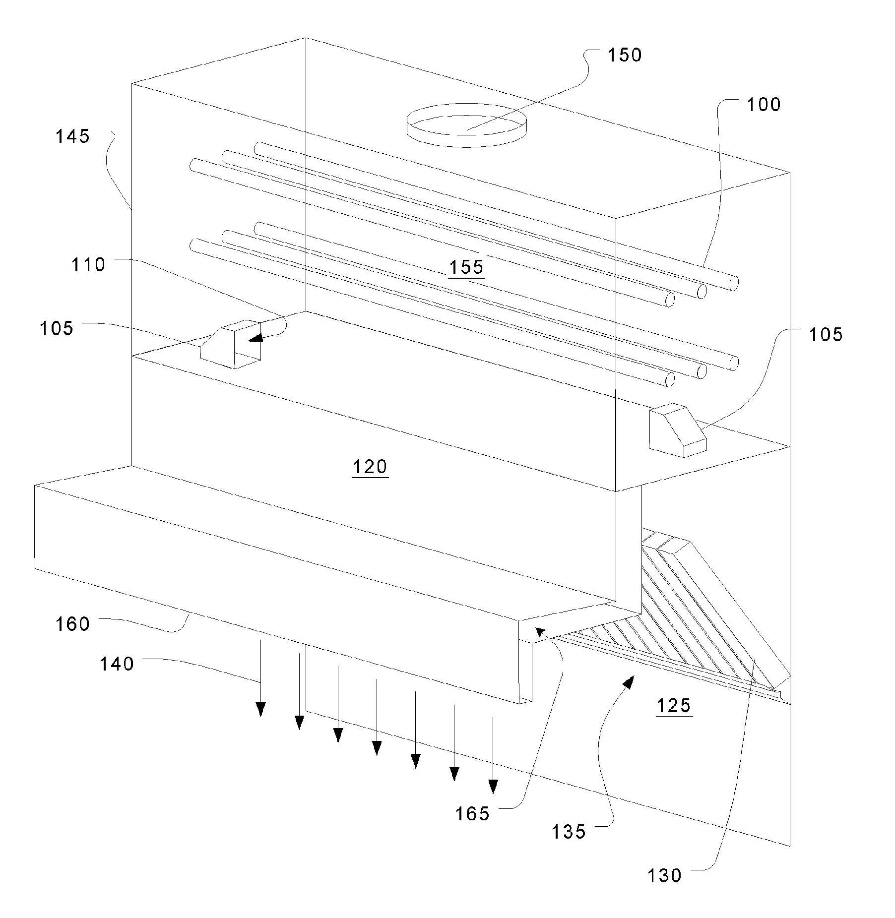
[0022] Referring to FIG. 1, exhaust fumes are drawn into an exhaust hood 160 and through a filter bank 135. Suction applied by an exhaust system (not shown) attached through a collar 150 draws the fumes through an ultraviolet treatment chamber 145. Ultraviolet lamps 100 are arranged to transmit light throughout the interior 155 of the ultraviolet treatment chamber 145. Exhaust fumes and air enter the ultraviolet treatment chamber 145 through opposed nozzles 105 with outlets 110.

[0023] The style of the exhaust hood 160 is a backshelf, but it could be any type of system that draws fumes containing hydrocarbons or organic particulates that can be treated with ultraviolet light. Most such hoods have a recess 125 that acts as a buffer for the exhaust stream and helps to match fluctuations in fumes with the uniform flow rate of the exhaust. As in some types of range hoods, an air curtain 140 may be generated by discharging clean air from a plenum 165 formed in a forward portion of the ho...


PUM

PropertyMeasurementUnit
Flow rateaaaaaaaaaa
Volumeaaaaaaaaaa
Residence timeaaaaaaaaaa

Abstract

An ultraviolet treatment chamber for treating exhaust streams, particularly those containing organic particulates, utilizes ultraviolet light energy very efficiently. This is done by setting up a circulating flow in a treatment plenum so that all of the effluent experiences a substantially uniform residence time without the need for baffles or other flow controllers that would block the ultraviolet light.

Description

CROSS REFERENCE TO RELATED APPLICATIONS [0001] This application claims priority to U.S. Provisional Application No. 60 / 662,507, filed Mar. 16, 2005.FIELD OF THE INVENTION [0002] The present invention relates to exhaust systems that withdraw fumes from a conditioned space and release at least partly cleaned air to the ambient atmosphere using ultraviolet light to reduce the contamination level. BACKGROUND OF THE INVENTION [0003] Exhaust hoods are used to remove air contaminants close to the source of generation located in a conditioned space. For example, one type of exhaust hoods, kitchen range hoods, creates suction zones directly above ranges, fryers, or other sources of air contamination. The exhaust stream from such applications often contain large quantities of particulates, particularly hydrocarbons such as oil droplets. Organic substances in the form of vapours or particles can also be formed by many production processes within various industries. For example, they can be gen...

Claims


Application Information

Patent Timeline
IPC IPC(8): F24C15/20
CPCY10S55/36F24C15/2035
Inventor BAGWELL, RICKBEARDSLEE, DARRENSCHROCK, DEREKLIVCHAK, ANDREY
Owner HALTON GROUP LTD
Why Eureka
Try Eureka