
Coupling members for closure devices and systems

a technology of closure device and member, applied in the field of various articles, can solve the problems of limiting the usefulness and/or life of conventional buckles and/or other closure devices, uncoupling of buckles, and limiting the usefulness and/or life of such straps, so as to prevent the male from uncoupling

Active Publication Date: 2014-05-08
BOA TECHNOLOGY
View PDF3 Cites 66 Cited by
  • Summary
  • Abstract
  • Description
  • Claims
  • Application Information

AI Technical Summary

Benefits of technology

The patent describes a brace that can be opened and closed about a patient's limb by attaching and unattaching male and female components. The components can be attached to the brace using methods like stitching, riveting, injection molding, adhesive bonding, and heat welding. When attached, the male and female components have a low profile to minimize contact with other objects. The brace can also be locked in place to prevent uncoupling of the components. The technical effect of this invention is an improved and versatile brace that allows for easy adjustment and secure fitting on a patient's limb.

Problems solved by technology

Conventional buckles and / or other closure devices, however, often are limited in there usefulness.
Such Velcro® surfaces, however, often get filled or cluttered with dirt and / or debris, which limits the usefulness and / or life of such straps.
The uncoupling of the buckle may be purposeful or accidental, such as when the buckle contacts nearby objects.
Releasing the tensioned article may cause the limb to be unsupported, which may subject the limb to damage, and / or may cause the user to trip, fall, or otherwise lose concentration during an activity.

Method used


Image

  • Coupling members for closure devices and systems
  • Coupling members for closure devices and systems
  • Coupling members for closure devices and systems

Examples


Embodiment Construction

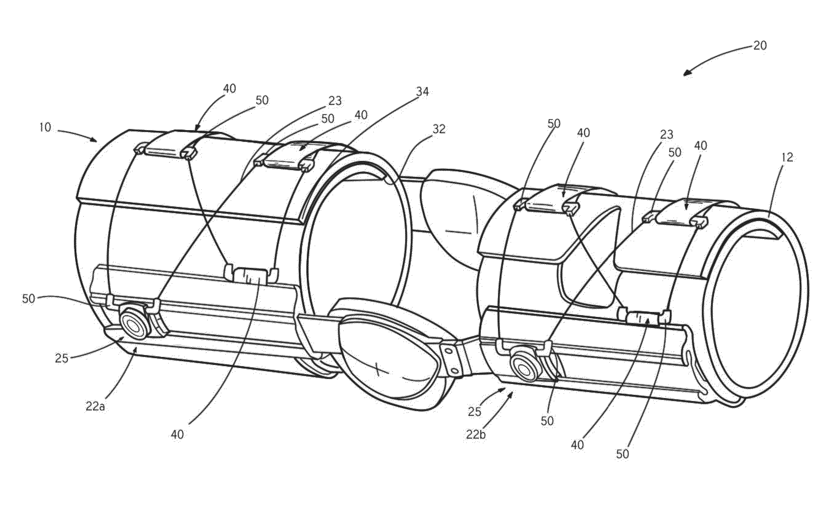
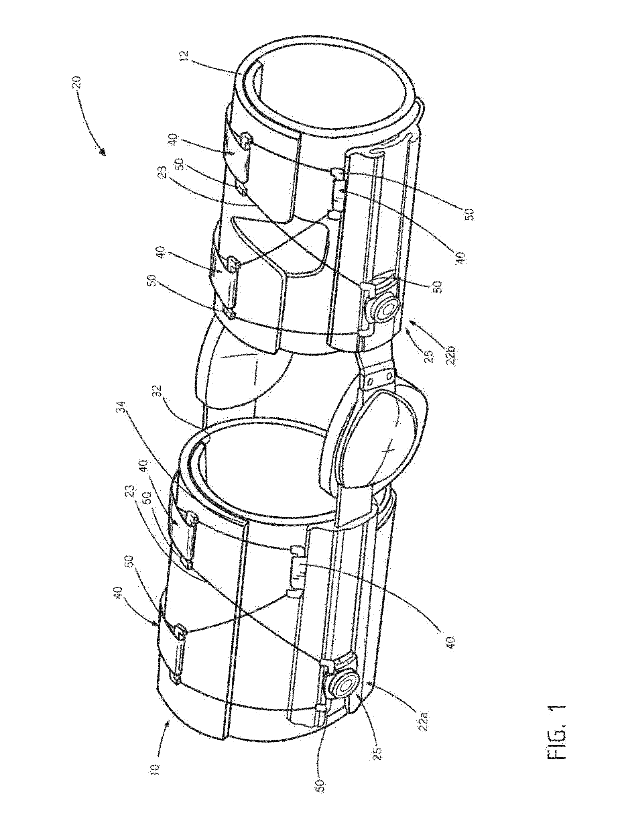
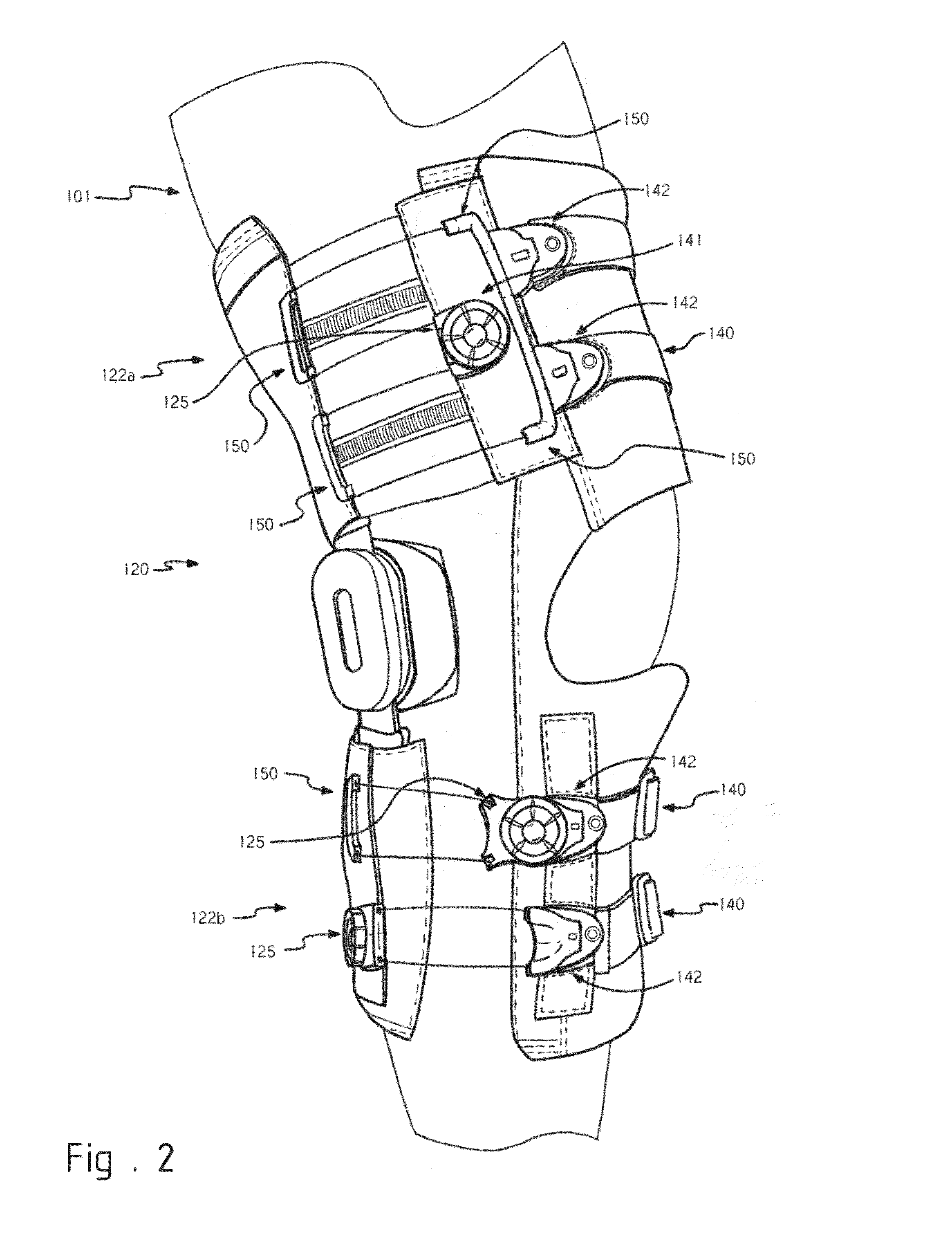
[0041]Embodiments described herein provide various closure devices or mechanisms (hereinafter detachable guides) that may be used to close various articles, such as braces, footwear, hats, gloves, or other apparel to allow a user to don and doff the article. For convenience in describing the embodiments, the detachable guides will be described generally as being coupled with braces to allow the braces to be quickly donned / doffed and / or tightened about a user's limb. Although the disclosure will focus mainly on braces, it should be realized that the detachable guides may be used for or with various other articles.

[0042]In some embodiments, the detachable guides may be used with lacing systems that include reel assemblies that close and tighten the brace about the user's limb. The detachable guides provide various improvements over conventional closure systems including: having a low profile when male and female components are coupled together; being intuitive and easy to use, being a...


PUM

PropertyMeasurementUnit
Pressureaaaaaaaaaa
Pressureaaaaaaaaaa
Tensionaaaaaaaaaa

Abstract

According to one embodiment, a coupling component includes a female component and a male component. The female component includes a main body portion and a coupling aperture. Similarly, the male component includes a main body portion and a coupling member. The coupling member that is mateable with the coupling aperture of the female component to couple the male and female components together. The main body portion of the male component includes a top surface and a relatively planar bottom surface. The coupling member includes a relatively planar top surface and a bottom surface. The relatively planar top surface of the coupling member is offset from the relatively planar bottom surface of the male component. The male and female components are non-releasable from a coupled engagement while under tension via a tension member.

Description

CROSS-REFERENCES TO RELATED APPLICATIONS[0001]This application claims priority to U.S. Patent Application No. 61 / 722,022 filed Nov. 2, 2012 entitled “COUPLING MEMBERS FOR CLOSURE DEVICES AND SYSTEMS,” the entire disclosure of which is hereby incorporated by reference, for all purposes, as if fully set forth herein.BACKGROUND OF THE INVENTION[0002]The present invention is related to coupling devices for various articles, such as braces, medical devices, shoes, clothing, apparel, and the like. Such articles often include coupling devices, such as buckles, straps, and the like, that allow the article to be placed and roughly fit about a limb. Conventional buckles and / or other closure devices, however, often are limited in there usefulness. For example, Velcro® straps and / or components are often employed in coupling devices. A common example invovles straps that may include Velcro® surfaces that allow the straps to be tensioned and folded back and coupled on itself. Such Velcro® surface...

Claims


Application Information

Patent Timeline
IPC IPC(8): A44B11/25B21D53/46
CPCB21D53/46A44B11/25A44B11/2588A43C11/165A61F5/01A43B3/122A43B5/0401Y10T24/40Y10T29/12
Inventor CAPRA, JAMESNICKEL, MICHAELBURNS, ROBERTWHITE, TAMARAHAMMERSLAG, GARY
Owner BOA TECHNOLOGY
Learn More