Pipe coupling device

a technology of coupling device and pipe, which is applied in the direction of hose connection, valve housing, coupling, etc., can solve the problems of pipe corrosion by impurities, affecting the connection of pipes, and difficult to connect pipes from which only small portions are possibl

Active Publication Date: 2011-06-23
CHOI YUK NAM
View PDF10 Cites 11 Cited by
  • Summary
  • Abstract
  • Description
  • Claims
  • Application Information

AI Technical Summary

Benefits of technology

[0015]It is an object of the present invention to provide a pipe coupling device that provides a sufficient coupling depth to connect pipes, from which even slig

Problems solved by technology

When it is intended to produce a long transport line, a number of coupling sites are required in the middle of the transport line due to the limited length of pipes.
In many cases, pipes tend to corrode by impurities settled therein or are damaged by external impact.
However, the prior art pipe coupling device connects pipes from which only portions containing settled impurities are cut out within a length range without departing from an allowable tolerance range of a currently available pipe coupling device.
Thus, the periphery of the settled portions is liable to corrode.
It is difficult to connect pip

Method used


Image

  • Pipe coupling device
  • Pipe coupling device
  • Pipe coupling device

Examples


Embodiment Construction

[0042]It should be noted that whenever possible, the same reference numerals will be used throughout the drawings and the description to refer to the same or like parts. In describing the present invention, detailed descriptions of related known functions or configurations are omitted in order to avoid making the essential subject of the invention unclear.

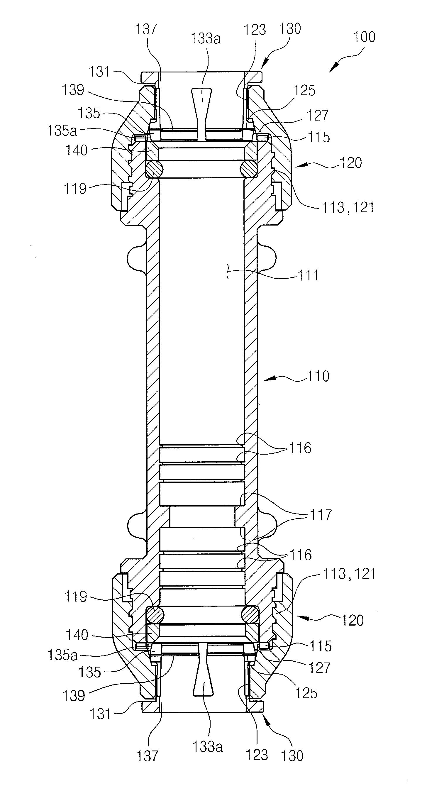
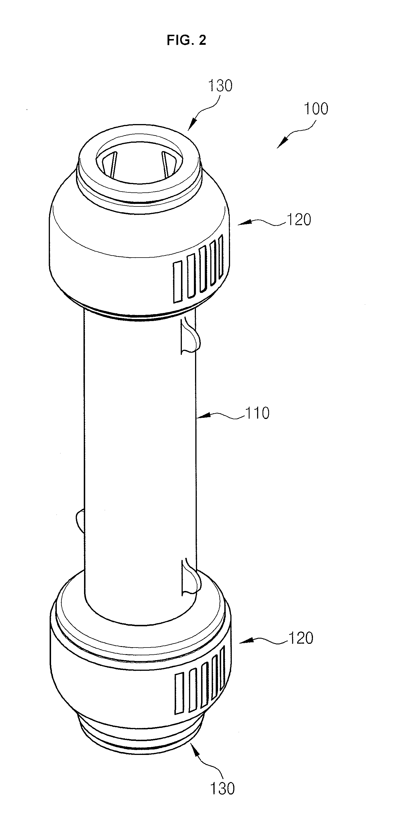
[0043]FIG. 2 is an assembled perspective view illustrating a pipe coupling device according to an embodiment of the present invention, FIG. 3 is an exploded perspective view illustrating the pipe coupling device of FIG. 2, FIGS. 4 and 5 are cross-sectional views illustrating pipe coupling devices according to embodiments of the present invention, FIG. 6 is an assembled cross-sectional view illustrating the pipe coupling device of FIG. 2, FIG. 7 is an exploded cross-sectional view illustrating the pipe coupling device of FIG. 2, FIGS. 8 to 10 are cross-sectional views illustrating pipe coupling devices according to embodiments of th...


PUM

PropertyMeasurementUnit
Flow rateaaaaaaaaaa
Depthaaaaaaaaaa
Heightaaaaaaaaaa

Abstract

A pipe coupling device is provided. The pipe coupling device includes a body part, fastening parts, and pressurizing parts. The body part has a multi-stepped insertion hole penetrating the central portion thereof, a stepped latching portion formed on the inner circumference of the insertion hole to limit the insertion depths of pipes, externally threaded portions formed on the outer circumference of both ends thereof, and first projections continuously formed on the upper surfaces of the externally threaded portions. Each of the fastening parts has an internally threaded portion formed on the inner circumference thereof and is screwed onto the externally threaded portion, a coupling hole penetrating the central portion thereof so as to be in communication with the insertion hole, a first inclined plane formed around the boundary between the internally threaded portion and the insertion hole, and second projections continuously formed on the lower surface of the first inclined plane to pressurize the first projections and to be engaged with the first projections when the fastening part is fastened to the body part. Each of the pressurizing parts has a stepped foot portion formed on the outer circumference of one side thereof so as to be introduced into the coupling hole, a pressurizing piece integrated with the stepped foot portion, a stepped latching portion formed on the outer circumference of the other side thereof, cut-away grooves formed on the outer circumferential surface of the pressurizing piece to elastically widen the pressurizing piece, and a pressurizing space formed in the central portion thereof. The first inclined plane of the fastening part fastened to the body part pressurizes the outer circumferential surface of the stepped latching portion, or the outer circumference of the stepped latching portion is moved inward along the first inclined plane and the pressurizing piece shrinks inward to pressurize the outer circumference of the pipe inserted into the pressurizing space when the pipe inserted into the pressurizing space is withdrawn.

Description

BACKGROUND OF THE INVENTION[0001]1. Field of the Invention[0002]The present invention relates to a pipe coupling device, and more specifically to a pipe coupling device that joins and connects pipes from which corroded or damaged portions are cut out.[0003]2. Description of the Related Art[0004]Piping work is generally carried out by cutting a plurality of pipes having various lengths and connecting the cut pipes together to form pipelines according to installation environments. Pipe coupling devices are used for the limited length of pipes and the necessity to change the position of pipelines during piping work.[0005]Main applications of pipes are water supply and drainage lines for the transport of water and hydraulic lines for the transport of fluids such as oil. In addition, pipes are used to transport gases and various raw materials such as powders.[0006]When it is intended to produce a long transport line, a number of coupling sites are required in the middle of the transport ...

Claims


Application Information

Patent Timeline
IPC IPC(8): F16L21/00
CPCF16K27/065F16L37/0925F16L19/086Y10T137/87909Y10T137/87708F16L37/0927F16L19/06F16L19/065F16L37/092
Inventor CHOI, YUK NAM
Owner CHOI YUK NAM
Why Eureka
Try Eureka