Scanning method and apparatus

a scanning method and apparatus technology, applied in the direction of instruments, specific gravity measurement, handling using diaphragms/collimeters, etc., can solve the problems of pipelines without insulation or coating, pipelines located underwater, and inconvenient inspection of the interior of pipelines by pigs, etc., to achieve greater structural strength, reduce the weight of the detector unit, and increase the thickness of the shielding material

Active Publication Date: 2018-02-20
TRACERCO LTD
View PDF83 Cites 17 Cited by
  • Summary
  • Abstract
  • Description
  • Claims
  • Application Information

AI Technical Summary

Benefits of technology

[0023]The source unit and detector unit may be mounted on a support in fixed relationship to one another or the detector unit may be movable relative to the source unit. It is greatly preferred that the source unit and detector unit are mounted in a fixed relationship when the apparatus is in operation. This enables the apparatus of the invention to provide a precise and fixed alignment of source and detector units so that modulation of the counts measured by the detectors can be attributed solely to the materials between the source and detector through which the radiation path passes. In this way, very small differences in the density of such materials can be detected, allowing the detection of small flaws or changes in the thickness of a pipeline wall. The source and detector unit are preferably mounted so that the detecting surface(s) of each of the detectors form a tangent to an arc having the source at its origin. The plurality of detector units are arranged in close proximity to each other. It is preferred that the array of detector units is arranged in the form of an arc having a radius centred on the centre of the object or structure to be scanned. The design of the detector unit preferably minimises the total distance on each detection path through each detector unit in order to make the array of detector units as compact as possible, whilst maintaining sufficient depth of the collimation and a detector for efficient detection of gamma photons on each path.
[0059]For operation underwater, it is preferred to increase the buoyancy of the apparatus by means of a buoyancy block. If used, the buoyancy block may be attached to the apparatus by means of a flexible attachment so that the flotation force produced can be balanced during movement of the apparatus. Additionally or as an alternative, spaces within the apparatus may contain a foam material in order to provide positive buoyancy to the apparatus. Parts of the apparatus may be coated in a resilient foam material, again for the purpose of providing buoyancy and also to protect the apparatus from physical damage, such as impact damage, and environmentally induced damage such as corrosion.

Problems solved by technology

Whilst these scanning methods are well-developed and have become common for medical scanning, scanning a dense structure such as a pipeline presents difficulties because the density of the pipeline material is such that radiographic scanning must be done using gamma radiation which is of sufficient energy to penetrate and pass through the structure so that at least some radiation can be detected after the beam has passed through the structure.
A known problem for the oil and gas production industry is the inspection of pipelines located underwater, in particular on the sea-bed.
Inspection of the interior of the pipeline by the use of pigs is not always possible, for example when the pipeline has varying diameter.
Inspection from outside the pipe may be carried out by ultrasonic methods, although this is not suitable for pipelines having an insulation or coating.
Furthermore, if a fan-shaped radiation beam is to be used to scan the pipe, many of the radiation paths pass through a chord of the pipe cross-section and therefore through a relatively large amount of the pipeline wall material, requiring a relatively high energy gamma source.
The use of heavy collimation on a large number of detectors necessitates a scanning apparatus which is very heavy and so rotation of the apparatus in a controlled and precise manner around a large pipeline becomes very difficult.
When the pipeline is horizontal, it becomes necessary to trench the pipe in order to allow sufficient space in which to move a scanning apparatus and so the use of large apparatus becomes expensive, particularly when the pipeline is located sub-sea.
All of these considerations bring particular problems to the application of high resolution x-ray tomography methods to the scanning of pipelines or other large structures with high energy gamma radiation.

Method used


Image

  • Scanning method and apparatus
  • Scanning method and apparatus
  • Scanning method and apparatus

Examples


Embodiment Construction

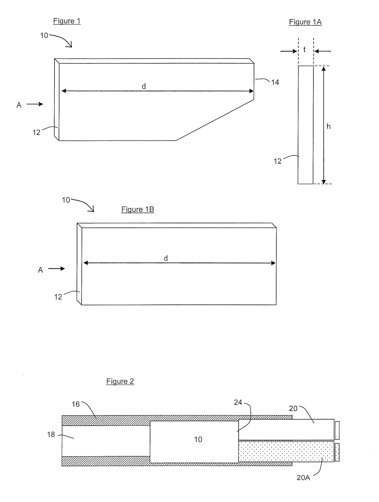
[0078]FIGS. 1 and 1A show a bismuth germinate (BGO) scintillator crystal 10 having a thickness t of 5 mm, a height h of 30 mm and a depth d of 75 mm. The detecting surface 12 is opposite the collecting surface 14. All surfaces of the bismuth germanate (BGO) scintillator crystal 10 except the detecting surface 12 and collecting surface 14 are coated in a highly reflective coating. FIG. 1B shows an alternative bismuth germanate (BGO) scintillator crystal 10.

[0079]FIG. 2 shows, a transverse cross-section through a detector unit 30, comprising a block of heavy alloy 16 which is highly attenuating to radiation, of the type used as shielding material for gamma radiation. The block of heavy alloy 16 has collimation channels 18 extending from the front face to the opposed rear face of the block of heavy alloy 16. In use, a bismuth germanate (BGO) scintillator crystal 10 is housed in the block of heavy alloy 16, with the detecting surface 12 of the bismuth germanate (BGO) scintillator crysta...


PUM

PropertyMeasurementUnit
depthaaaaaaaaaa
depthaaaaaaaaaa
depthaaaaaaaaaa

Abstract

The invention discloses a scanning method and apparatus suitable for scanning a pipeline or process vessel in which a beam of gamma radiation from a source is emitted through the vessel to be detected by an array of detectors which are each collimated to detect radiation over a narrow angle relative to the width of the emitted radiation beam.

Description

BACKGROUND OF THE INVENTIONField of the Invention[0001]The present invention relates to a method of scanning a structure to detect changes in density by means of detecting radiation emitted by a radiation source by a radiation detector.DESCRIPTION OF THE RELATED ART[0002]Methods of imaging objects and animals by X-ray tomography and positron-emission tomography are well-known, particularly in the field of medical imaging for diagnostic purposes. U.S. Pat. No. 4,338,521 describes an X-ray scanner for use in computerised tomography which has a detector comprising an array of detector modules, comprising a plurality of photodiodes and a plurality of scintillator crystals and a radiation beam collimator to direct collimated radiation to the scintillator crystals. A fan-shaped beam of x-rays from an x-ray source is directed through a patient to be detected by the detector. The source and detector are rotated around the patient to provide the data from which a tomographic image may be con...

Claims


Application Information

Patent Timeline
Patent Type & Authority Patents(United States)
IPC IPC(8): G01N23/04G01T1/20G21K1/02G01N9/24G01T1/164
CPCG01N23/046G01N9/24G01T1/2018G21K1/02G01T1/164G01N2223/419G01T1/2019G01T1/20185G01T1/20182G01T1/202G01T1/29G01T1/2914G01T1/20G01V5/005G01N2223/5055G01N23/18G01N23/06G01N23/087G01N23/04G01N23/083G01V5/0016
Inventor BOWDON, CHRISTOPHERFEATONBY, PAUL DAVIDHOWSTAN, JAMES STEPHENJACKSON, PETERJAMES, KENNETHRONCHI, EMANUELE
Owner TRACERCO LTD
Why Eureka
Try Eureka