PTC airflow heater

a technology of airflow heater and airflow outlet, which is applied in the field of heaters, can solve the problems of not having a heat controller function, easy to malfunction, and relatively short life of the warmer, and achieve the effect of minimizing the space of wiring connection, reducing the overall size of the housing, and minimizing the length of the electric wire usag

Inactive Publication Date: 2008-05-29
GAO TIANYU
View PDF11 Cites 79 Cited by
  • Summary
  • Abstract
  • Description
  • Claims
  • Application Information

AI Technical Summary

Benefits of technology

[0007]A main object of the present invention is to provide an airflow heater with an advanced heat generating arrangement structure so that the length of the

Problems solved by technology

Such a conventional warmer does not have a heat controller function.
Therefore, the life span of the warmer is relatively short and it is easy to malfunction and is not safe to use.
Since most of the temperature control is provided on top of the housing, the space for disposing the PTC heat generator is relative

Method used


Image

  • PTC airflow heater
  • PTC airflow heater
  • PTC airflow heater

Examples


Embodiment Construction

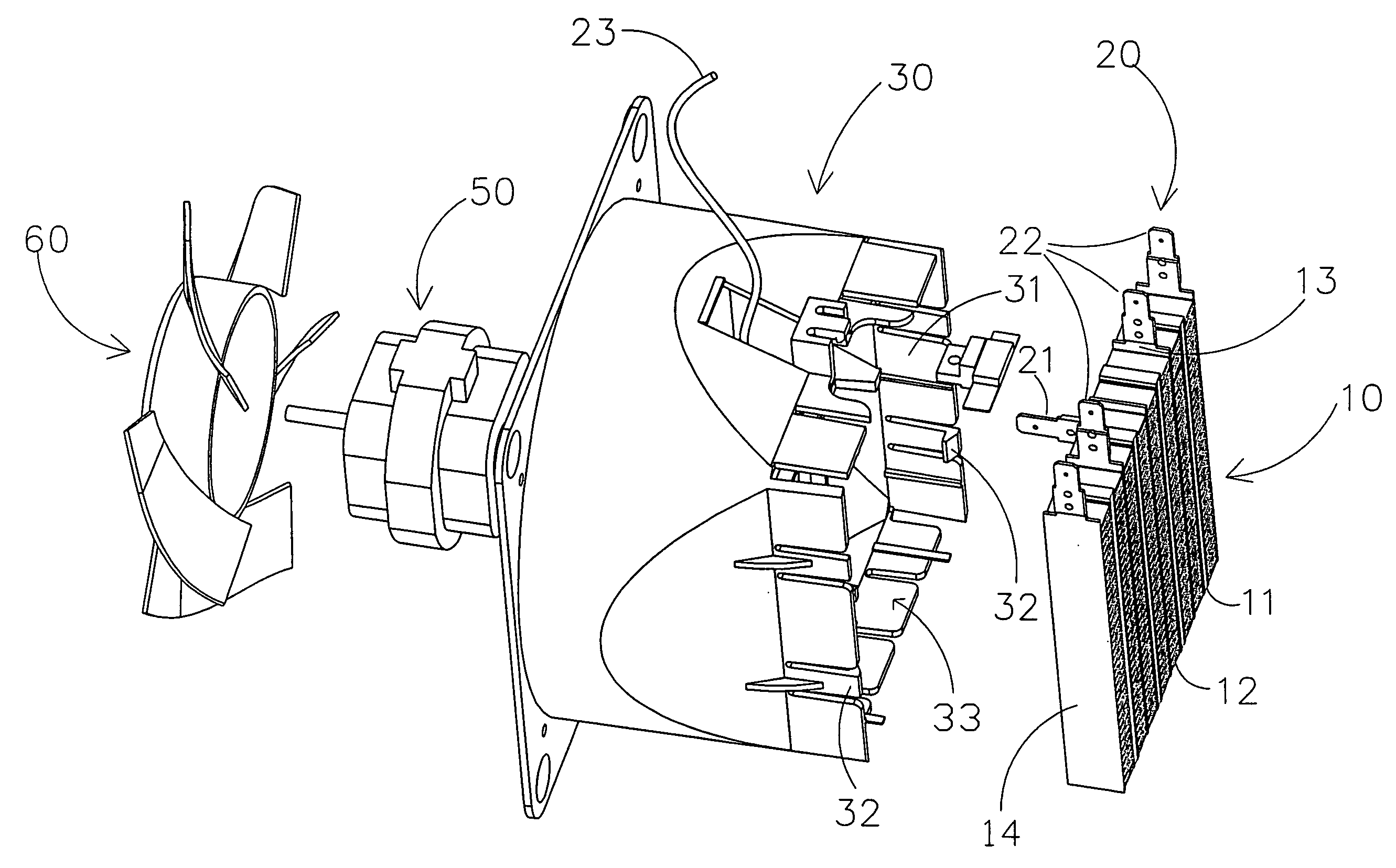
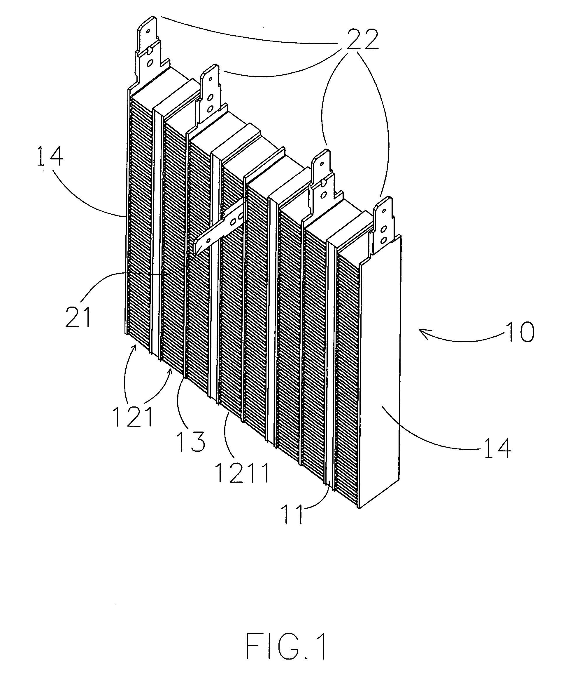
[0024]Referring to FIGS. 1 to 7 of the drawings, a PTC airflow heater according to a preferred embodiment of the present invention is illustrated, wherein the PTC airflow heater comprises a housing 70, a PTC heat generator 10 received in the housing 70, a n air source supported in the housing 70 at a position behind the PTC heat generator 10 for generating a flow of air towards the PTC heat generator. The PTC airflow heater further comprises a control arrangement supported at an upper portion of the housing 70 to control the PTC heat generator 10.

[0025]As shown in FIG. 7, the housing 70 comprises a front casing 71 and a rear casing 72 mounted thereto to define a receiving cavity between the front and rear casings 71, 72.

[0026]The air source comprises a fan blade 60 and a motor 50 driving the fan blade 60 via an output shaft to rotate so as to generate a flow of air towards the PTC heat generator 10. The control arrangement comprises a control unit 80 electrically connected between a...


PUM


Abstract

An airflow heater includes a housing, a control arrangement supported at an upper portion of the housing, an air source for generating a flow of air, a PTC heat generator for generating heat, and a terminal unit including an upward terminal connector upwardly extended from the PTC heat generator to align with the control arrangement and a sideward terminal connector rearwardly extended from the PTC heat generator to minimize a distance between the terminal unit and the control arrangement for electrical connection. The upward terminal connector and the sideward terminal connector are electrically connected to the control arrangement. The air source and the PTC heat generator are activated by the control arrangement for generating the air towards the PTC heat generator and for generating the heat respectively, such that when the air passes through the PTC heat generator, the air is heated up before exiting the housing.

Description

BACKGROUND OF THE PRESENT INVENTION[0001]1. Field of Invention[0002]The present invention relates to a warmer, and more particularly to a heat airflow heater which uses an advance heat generating connector structure so as to reduce the overall material cost and to simplify the assembling configuration.[0003]2. Description of Related Arts[0004]A conventional warmer, as a common house appliance, is adapted for generating a flow of heated air. Heated air is blown out to the environment such a room can be kept at a comfortable temperature. The warmer usually uses a heat generator as a heat source which is embodies as one of an electric wire having a predetermined resistance, a heat generating panel, and a heat generating tube for generating heat. Such a conventional warmer does not have a heat controller function. Therefore, the life span of the warmer is relatively short and it is easy to malfunction and is not safe to use. Another type of conventional warmer uses a PTC (Positive Tempe...

Claims


Application Information

Patent Timeline
IPC IPC(8): F24H3/02F24D15/02
CPCF24H3/0417F24H9/2071F24H9/1872F24H15/345F24H15/37
Inventor GAO, TIANYU
Owner GAO TIANYU
Why Eureka
Try Eureka