Filtration element and method of constructing a filtration assembly

a technology of filtration elements and components, applied in the field of coupling, can solve the problems of imposing significant restrictions on filtration capability, difficult to insert or pull the element into the housing, or to remove it when necessary for inspection or replacement, and compound drawbacks, so as to facilitate and securely coupling the filtration element, prevent decoupling, and minimize the contact area of the brin

Inactive Publication Date: 2006-04-06
KOCH MEMBRANE SYST
View PDF9 Cites 14 Cited by
  • Summary
  • Abstract
  • Description
  • Claims
  • Application Information

AI Technical Summary

Benefits of technology

[0013] The present invention is directed to an apparatus and method for easily and securely coupling filtration elements while minimizing the contact area of the brine with the filtration assembly housing. Each coupler includes a center support with anti-telescoping spokes extending from the center to a rim. Raised pads or skis are spaced around the perimeter of the outer surface of the rim, and include receptacles for receiving a keeper link. A channel is formed in each face of the rim for receiving a compressible seal. Thus, adjoining couplers can be interlocked by placing a seal in the face-to-face channels, aligning the skis and receptacles on each coupler, and placing keepers in the receptacles to interlock and join the couplers and prevent decoupling during element insertion and removal. When inserted into a filtration assembly housing, the skis minimize the contact area with the housing, thus reducing the frictional force between the coupler and the housing. The skis also allow for a single low-profile brine seal to be used for a plurality of elements resulting in less frictional resistance with the housing than is encountered when multiple brine seals are utilized. The single brine seal according to the present invention may be inserted and withdrawn from the same end of the housing. Thus, multiple filtration elements may be securely joined and easily inserted into, or removed from, a filtration assembly housing utilizing fewer seals and requiring 50% less “free” floor space.

Problems solved by technology

However, the configuration of the known art imposes significant restrictions on filtration capability.
For instance, the friction fit of the protruding brine seal on the outer perimeter of large diameter filtration elements makes it difficult to insert or pull the element into the housing, or to remove it when necessary for inspection or replacement.
This drawback is compounded when attempting to insert or remove multiple filtration elements all having brine seals joined end to end into or from the housing of a filtration assembly.
Increasing the force used to insert or remove the filtration elements may result in damage to the filtration elements.
The telescoping problem also increases with increasing diameters.
Thus, if a brine seal is damaged during the assembly process, not only is the sealing function compromised, the filtration element may be able to move relative to an adjoining element and the integrity of the separation process may be compromised.
This construction does not lock the elements together so they can be pulled through a housing, and it does not provide a positive compression seal between adjoining elements.

Method used


Image

  • Filtration element and method of constructing a filtration assembly
  • Filtration element and method of constructing a filtration assembly
  • Filtration element and method of constructing a filtration assembly

Examples


Embodiment Construction

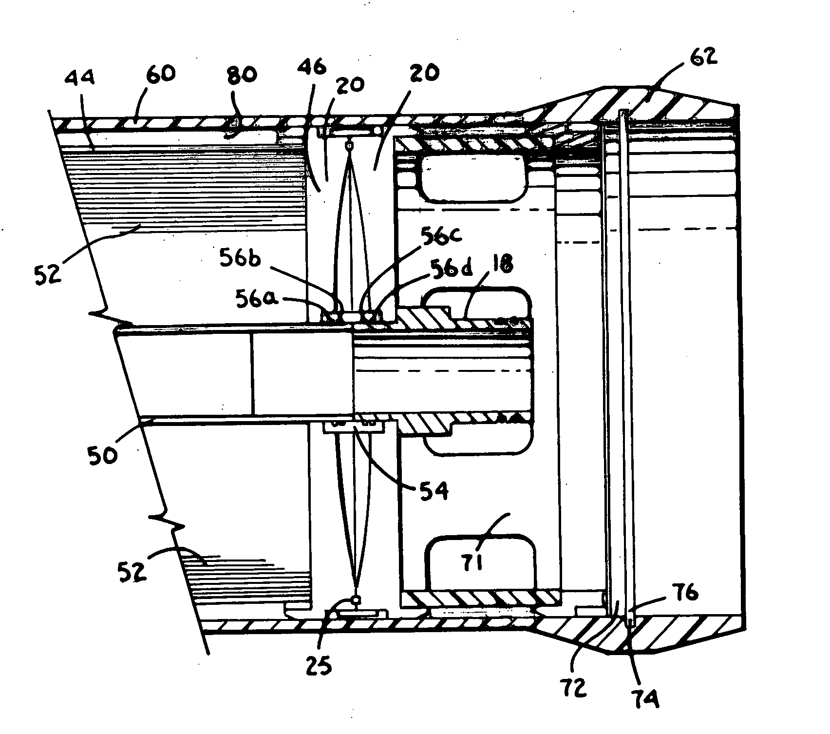
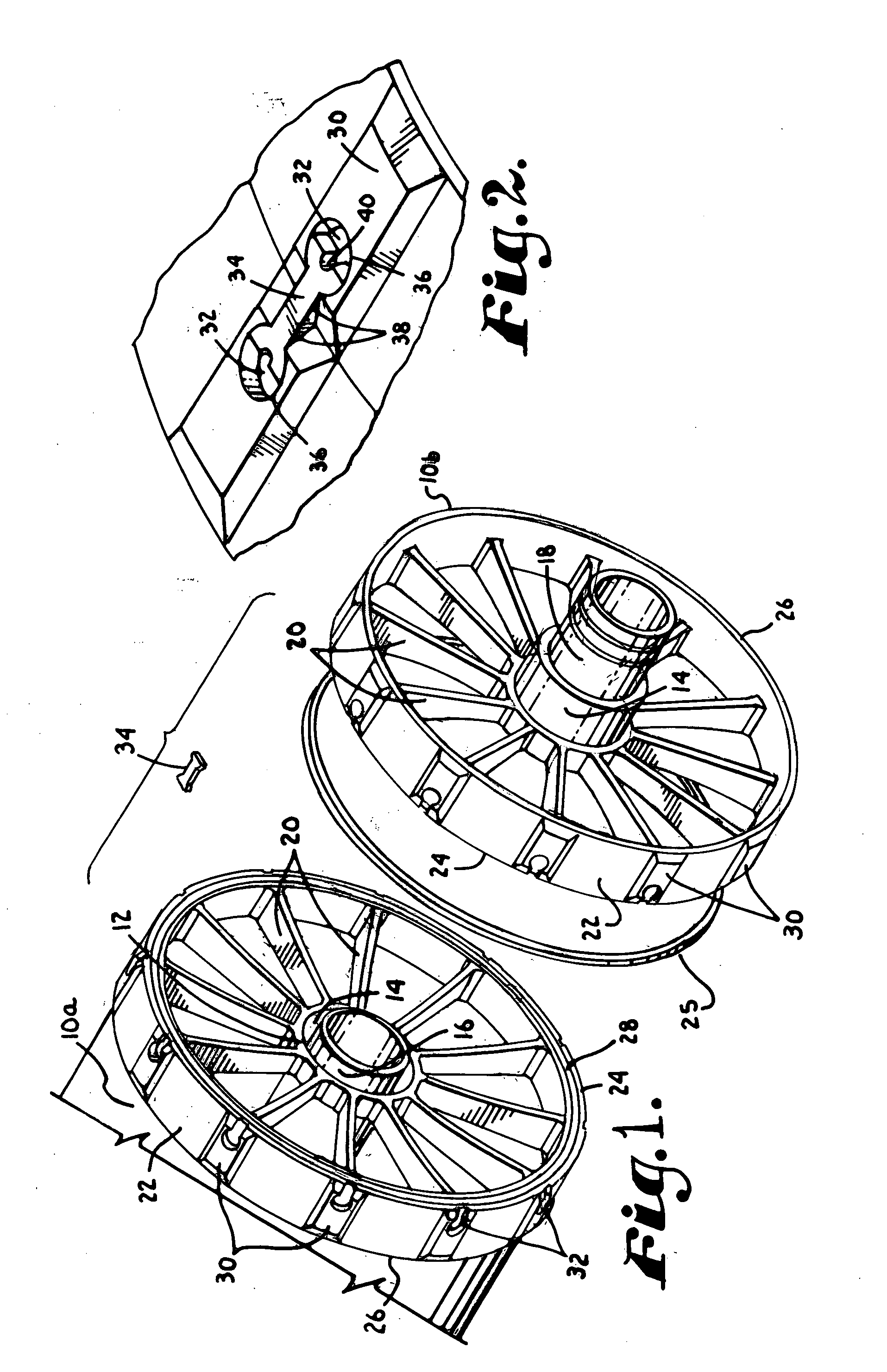
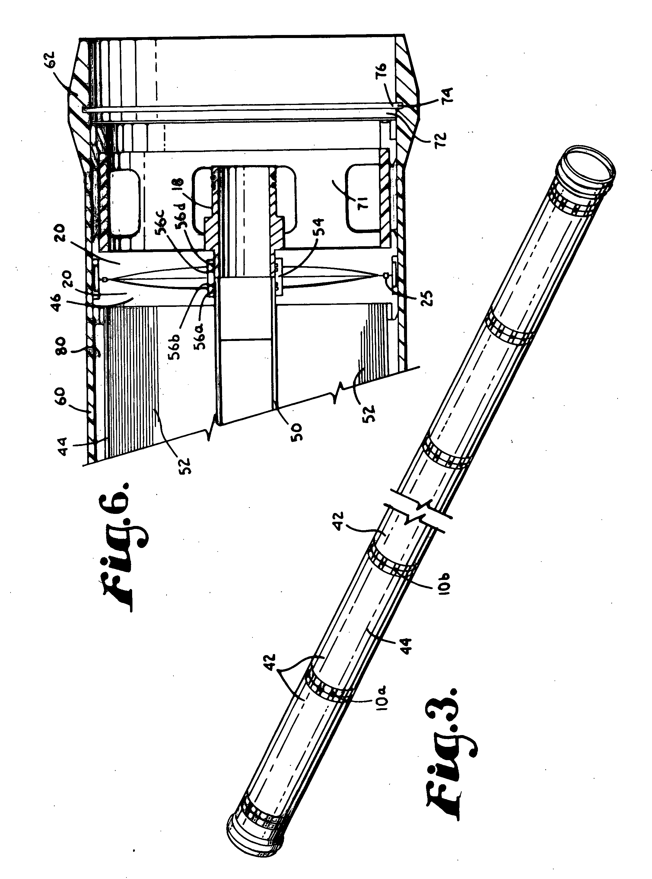
[0024] Couplers in accordance with an exemplary embodiment of the present invention are depicted in FIG. 1. Each coupler 10a, 10b includes a cylindrical center support 12 having an inner surface defining a circular opening 14. As shown, a permeate tube 16, typically combined with a permeate adapter 18 may pass through circular opening 14. Spokes 20 extend radially outward from the outer surface of center support 12 to the inner surface of a cylindrical rim 22 which encircles and joins to the outer ends of spokes 20. As can be better seen in the cross-sectional view of FIG. 6, the front edge of each spoke 20 has a slightly concave taper, with the rear edge of each spoke 20 being substantially straight. Returning to FIG. 1, rim 22 has outer and inner rim faces 24, 26. A generally U-shaped channel 28 extends around the perimeter of outer face 24 for receiving a complementary configured compressible seal 25.

[0025] Looking still to FIG. 1, raised pads or skis 30 extend around the outer ...


PUM

PropertyMeasurementUnit
radiusaaaaaaaaaa
compressibleaaaaaaaaaa
cross-sectional dimensionaaaaaaaaaa

Abstract

A coupler for a spiral membrane filtration element having a spiral membrane enclosed within a rigid outerwrap includes a center support, a plurality of spokes extending outwardly from the center support, a circular rim coupled with the spokes, with the face of the rim being perpendicular to the axis of the overwrap. The rim includes a channel on its face for receiving a compressible seal, and a plurality of receptacles around its outer surface for joining two face-to-face adjacent couplers when a pair of aligned keepers is place in each receptacle. Exemplary embodiments of the coupler and filtration elements and filtration assemblies are provided, as well as an associated method.

Description

CROSS-REFERENCE TO RELATED APPLICATIONS [0001] Divisional filed out of application Ser. No. 10 / 754,908, filed Jan. 9, 2004 which is a Continuation-in-Part of application Ser. No. 10 / 640,407, filed Aug. 13, 2003 (now abandoned), the specification and claims of which are hereby incorporated by reference.STATEMENT REGARDING FEDERALLY SPONSORED RESEARCH OR DEVELOPMENT [0002] Not Applicable. BACKGROUND OF THE INVENTION [0003] 1. Field of the Invention [0004] The invention relates generally to filtration, and more particularly to a coupler for joining filtration elements. [0005] 2. Description of Related Art [0006] Filtration membranes are used for the removal of unwanted particles or organisms from various types of fluids. Typical uses for filtration membranes include treatment and purification of drinking water, cleaning and treatment of wastewater for disposal or re-use, sludge de-watering, desalination, and clarification of juices, wines, and beverages. Filtration membranes include sp...

Claims


Application Information

Patent Timeline
Patent Type & Authority Applications(United States)
IPC IPC(8): B01D63/12B01D63/00B01D63/10F16L55/24
CPCB01D63/10F16L55/24B01D63/12B01D63/106Y02A20/131B01D63/00
Inventor COLBY, DAVID M.LESAN, FREDERICK K.FRANKS, ALAN M.HSIEH, CHANG-LIMUKHERJEE, ANJAN KUMAR
Owner KOCH MEMBRANE SYST
Why Eureka
Try Eureka