Fixing device and image forming apparatus incorporating the same

a technology of fixing device and image forming apparatus, which is applied in the direction of electrographic process apparatus, ohmic resistance heating, instruments, etc., can solve the problems of defective image, damaged surface of fixing roller (the heating roller and/or the press roller), and prone to wind around the heating roller. , to avoid defective image and sheet jamming, the effect of preventing the damage of the surface of the fixing member

Inactive Publication Date: 2005-06-09
SEIKO EPSON CORP
View PDF2 Cites 17 Cited by
  • Summary
  • Abstract
  • Description
  • Claims
  • Application Information

AI Technical Summary

Benefits of technology

[0007] It is therefore an object of the invention to provide a fixing device capable of dispensing with such a peeler that forcibly peels off a sheet medium, thereby preventing the surface of a fixing member being damaged, and avoiding the defective image and the sheet jamming due to the unstable fixation of the toner image.
[0008] It is also an object of the invention to provide a fixing device in which a structure for guiding the sheet medium is simplified, thereby reducing the costs and the size of the fixing device and an image forming apparatus incorporating the fixing device.
[0017] With this configuration, the recording medium is curled in such a direction separating from the heating roller at the exit of the fixing nip portion, so that the recording medium ejected from the fixing nip portion is conveyed without being wound on the heating roller thereby dispensing with such a peeler which forcibly peels off the recording medium. Further, since only the leading end portion of the recording medium is brought into contact with the slope portion, that is, the toner image fixed on the recording medium is not brought into contact with the guide member, the transfer or adhesion of the toner image onto the guide member can be reliably avoided.
[0024] With this configuration, the rigidity of the heating roller is enhanced and the toner peelability from the heating roller is improved.
[0029] With this configuration, the contact area between the recording medium and the guide member can be minimized, so that the transfer or adhesion of tile toner image onto the guide member can be further reliably avoided.
[0031] With this configuration, stress applied to the recording medium passing through the guide member ran be reduced, so that the damage on the recording medium can be avoided.

Problems solved by technology

In the former type of the fixing device, when the sheet medium is passed through the fixing nip portion to perform the fixation of the unfixed toner image, the sheet medium is curled along the outer periphery of the heating roller and becomes liable to wind around the heating roller.
However, in such a configuration that the peeler comes in slide contact with the fixing roller, irrespective of the degree of the sliding pressure, the surface of the fixing roller (the heating roller and / or the press roller) is liable to be subjected to damage, wear, and deterioration.
When the peeler disclosed in the above publications comes in slide contact with such an unfixed toner image, sliding traces would be left on the image, or the unfixed toner would be transferred onto the peeler, thereby causing a defect on the obtained image, or the unfixed image would adhere the peeler, thereby interfering the conveyance of the sheet medium and causing the sheet jamming.

Method used


Image

  • Fixing device and image forming apparatus incorporating the same
  • Fixing device and image forming apparatus incorporating the same
  • Fixing device and image forming apparatus incorporating the same

Examples


first embodiment

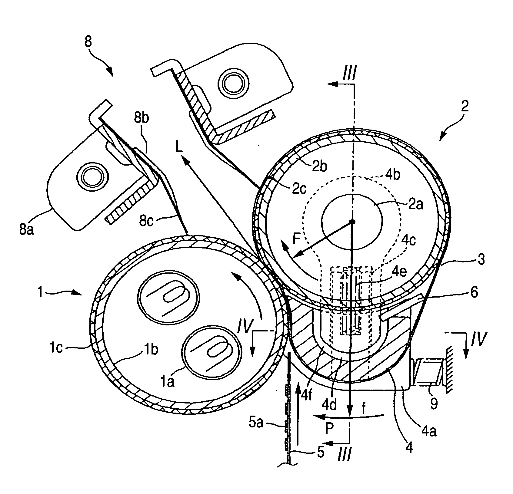
[0070]FIG. 1 shows the invention. A heating roller 1 comprises: a tubular base 1b having an outer diameter of and 25 mm and a thickness of 0.7 mm; an elastic body 1c of a thickness of 0.4 mm covering an outer periphery of the tubular base 1b; and two columnar-shaped halogen lamps 1a of 1050 W as a heating source housed inside the tubular base 1b. A press roller 2 is opposed to the heating roller 1 to provide pressure against the heating roller 1. A surface of the press roller 2 is made harder than the elastic body 1c of the heating roller 1.

[0071] A heat-resistant belt 3 is an endless belt member suspended by the press roller 2 and a belt stretcher 4 and circulated on the outer peripheries of these members while being sandwiched between the heating roller 1 and the press roller 2 to form a fixing nip portion. The heating roller 1 and the press roller 2 are rotated in the direction of arrow in this figure to circulate the stretched belt 3. A sheet medium 5 on which an unfixed toner i...

seventh embodiment

[0152]FIG. 22A shows the invention. Elements similar to those in the fist embodiment will be designated by the same reference numerals and the repetitive explanations for those will be omitted.

[0153] In this embodiment, the belt 3 and the belt stretcher 4 are omitted. The fixing nip portion is formed by the press contact between the heating roller 1 and the press roller 2.

[0154]FIG. 22B shows an eighth embodiment of the invention. Elements similar to those in the first embodiment will be designated by the same reference numerals and the repetitive explanations for those will be omitted.

[0155] In this embodiment, a press member 62 is provided instead of the press roller 2. The press member 62 comprises an elastic member 62c which presses the belt 3 against the heating roller 1 to form a wide fixing nip portion, and a separator 62d having a curvature radius smaller than that of an outer periphery of the heating roller 1 to locally deform the elastic surface layer 1C of the heating r...


PUM


Abstract

In a fixing device for fixing a toner image onto a recording medium, a healing roller is provided with an elastic layer formed on an outer periphery thereof. An endless belt is adapted to be circulated. A press member presses a part of the endless belt against the heating roller so as to deform the elastic layer, thereby forming a fixing nip portion through which the recording medium it passed. A guide member has a slope portion extended so as to close to a tangential line defined at a press contact position between the heating roller and the press member, as is being away from the exit of the fixing nip portion. A fixing pressure generated at the exit of the fixing nip portion is greater than a fixing pressure generated at an entrance of the fixing nip portion.

Description

BACKGROUND OF THE INVENTION [0001] The present invention relates to a fixing device comprising, a heating roller having an elastic surface layer and incorporating a heat source therein; a press roller opposed to the heating roller so as to provide pressure against the heating roller; and a heat-resistant belt circulated while being sandwiched between the heating roller and the press roller to form a fixing nip portion, wherein a sheet medium on which an unfixed toner image is formed is passed through the fixing nip portion to fix the unfixed toner image on the sheet medium. [0002] The present invention also relates to a fixing device comprising: a heating element having a flat surface; a press roller opposed to the flat surface so as to provide pressure against the heating element; and a heat-resistant belt circulated while being sandwiched between the flat surface and the press roller to form a fixing nip portion, wherein a sheet medium on which an unfixed toner image is formed is ...

Claims


Application Information

Patent Timeline
Patent Type & Authority Applications(United States)
IPC IPC(8): G03G15/20
CPCG03G2215/2009G03G2215/2022G03G15/2028
Inventor ARUGA, TOMOEIKUMA, KEN
Owner SEIKO EPSON CORP
Why Eureka
Try Eureka