Controlled discharge ostomy appliance and shield therefor

a technology of ostomy and shield, which is applied in the field of controlled discharge ostomy appliance and an auxiliary device therefor, can solve the problems of reducing the efficacy of the seal, and achieve the effects of reducing the damping characteristic of the seal, reducing the damping characteristic, and facilitating the change of the shape of the seal

Active Publication Date: 2012-07-12
CONVATEC TECH INC
View PDF8 Cites 56 Cited by
  • Summary
  • Abstract
  • Description
  • Claims
  • Application Information

AI Technical Summary

Benefits of technology

[0012](ii) the final shape adopted by the seal might not be that matching a natural shape of the stoma, because both the seal and the stoma are subjected to the high contact pressure. This may reduce the efficacy of the seal; and
[0017]In addition to more comfortable fitting, deploying the seal into contact with the stoma from a non-deployed condition may achieve a better fitting shape of the seal, than if the seal is forced to compress when fitted in a fully-deployed condition. It is believed that this better fitting shape may be a result of (i) the seal being able to drape around the stoma more freely as contacts the stoma progressively during deployment, and / or (ii) avoiding or reducing the extent to which the stoma is itself deformed from its natural shape by contact pressure on the stoma.
[0020]In a preferred form, the seal displacer is manipulable by a user to displace the seal to the non-deployed position at a time chosen by the user. The seal displacer may be comprised in an auxiliary device for the appliance. The auxiliary device may, for example, be in the form of a protector or shield or other packaging for the appliance. Use of the seal displacer enables the seal to be manipulated with the protector still assembled to the appliance, thereby avoiding risk of soiling or damaging the seal surface. The seal displacer is releasable from the appliance, whereupon the seal begins to deploy under the seal's self-urging effect.
[0031]Prior to first use, the first and second coupling members are retained in the unlocked position by the co-operating retainers. Upon first use, in order to assemble the appliance to the counterpart coupling element, the appliance is pressed against the counterpart coupling element. The press-fit coupling force being smaller than the first retention strength generally encourages a two-stage engagement effect. The counterpart coupling element is able to engage the coupling formation generally prior to the pressure causing relative displacement between the first and second members to the locked position. Once in the locked position, the bracing portion of the second member braces the coupling formation against deflection, thereby locking or securely attaching the appliance to the counterpart coupling element. In order to separate the appliance, the frangible portion is torn or broken, releasing the bracing effect. The first member may remain at least temporarily coupled to the counterpart coupling element, at least until an external force is applied to separate the two. However, the release of the bracing effect means that it becomes easier to separate the first member from the counterpart coupling element. Optionally, the second member may be moved away from the first member, exposing the first member and facilitating separation. The second member may be shaped or configured so as to at least partly shroud the first member at least when in the locked position.
[0034]The body-facing portion of the appliance typically includes at least a stoma seal for sealing engagement with a stoma in use, and a mounting device for mounting the appliance in an operative position at a stoma. The seal is, by its nature delicate and vulnerable to damage. Damage to the seal surface may reduce the efficacy of the stoma seal, and lead to premature leakage of stool during the normal wear-life of the appliance. The protector can also keep the surface of the seal clean, while enabling the appliance (with the protector assembled thereto) to be carried in a suitable bag, such as a hand-bag or brief-case, until fitted.

Problems solved by technology

The problem is that the damping characteristic is designed specifically to resist such dynamic compression of the seal, and instead to generate a counter force pressing on the stoma.
This can result in three issues:
This may reduce the efficacy of the seal; and

Method used


Image

  • Controlled discharge ostomy appliance and shield therefor
  • Controlled discharge ostomy appliance and shield therefor
  • Controlled discharge ostomy appliance and shield therefor

Examples


first embodiment

[0095]A second aspect of the preferred embodiment relates to a coupling member arrangement for making a press-fit with a body-side coupling member for fitting the appliance at a stoma. This aspect may be used in combination with the first aspect, or independently of the first aspect. The following description focuses on a coupling for the appliance, but this embodiment may also use any combination of features from the first embodiment as if described in whole combination.

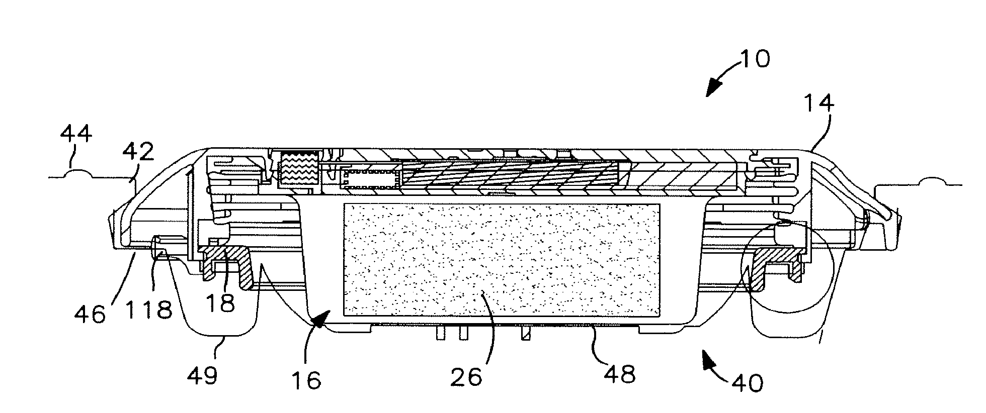
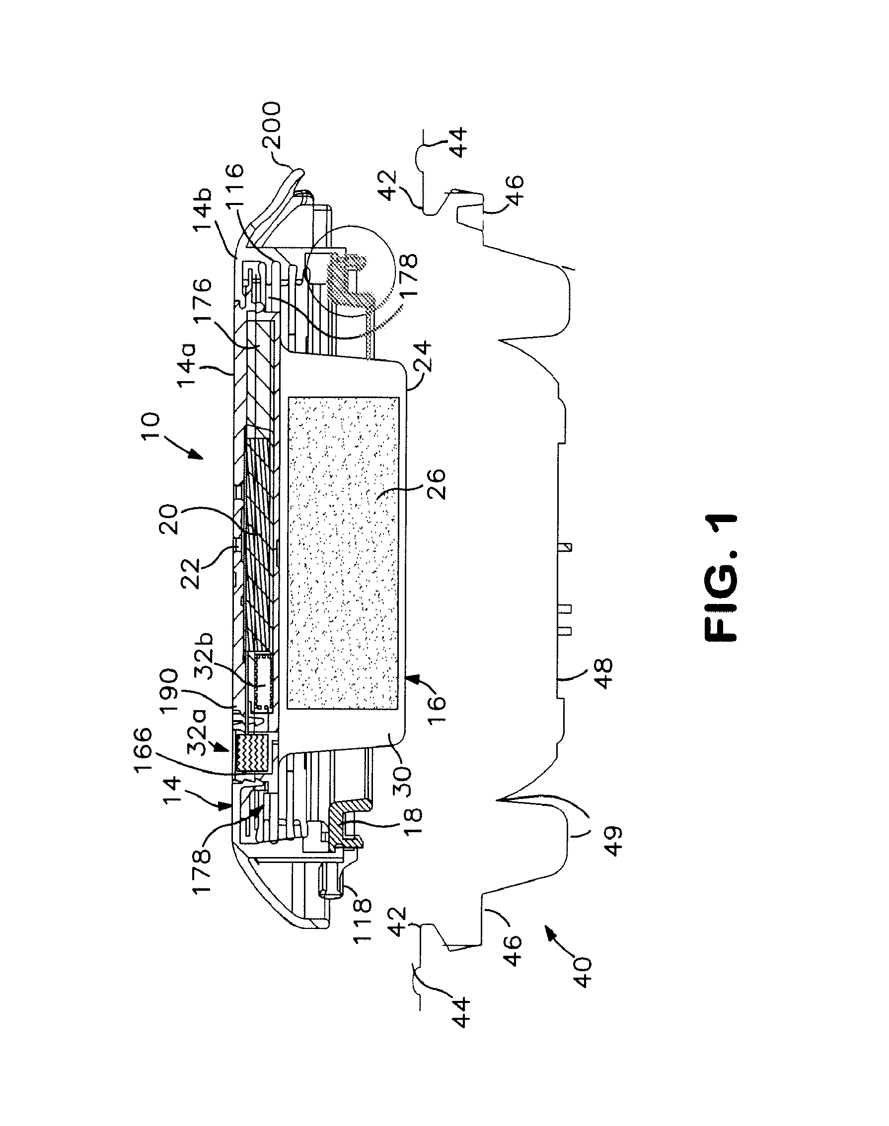
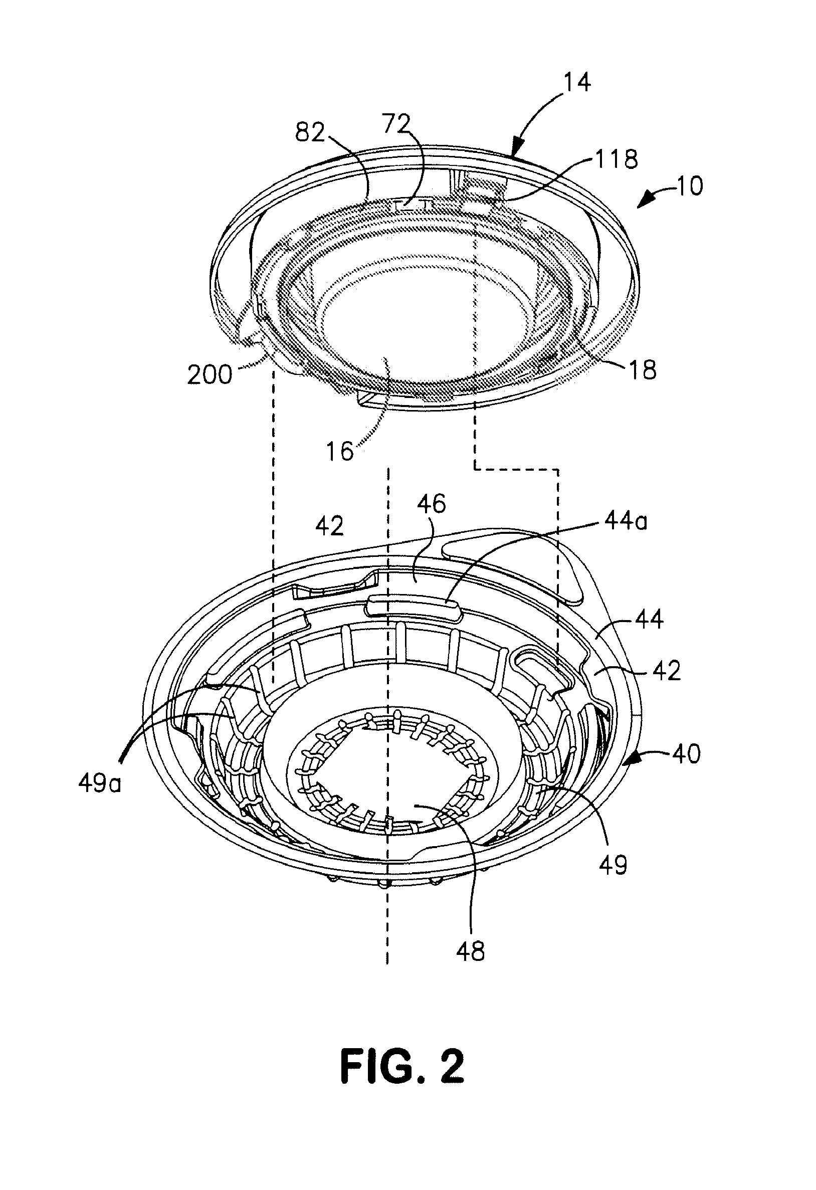
[0096]As best seen in FIGS. 9-11, the mounting device comprises a first member (first coupling member or appliance-side coupling member) 18 distinct from the cover 14 (second member). The first member 18 is of closed loop shape (e.g. annular in this embodiment). The first member 18 has a base 70 carrying a coupling formation for mechanically engaging the body-side coupling member 54 of the body fitment 50. The coupling formation comprises a plurality of lugs 72 depending from the base 70 at spaced apart positions ar...

second embodiment

[0115]The invention envisages various possible designs for releasing or relaxing the attachment to the body-side coupling member 54 when the user desires to remove the appliance 10 after it has been used. In one form (not shown), the cover 14 may be shiftable from the locked position back to the unlocked position, in order to remove the bracing effect on the lugs 72, and allow easier separation. However, in the second embodiment, the appliance 14 includes the following additional features:

(i) a single-use feature of the cover 14 for obstructing attachment of the device to the body fitment 50 more than once. The single-use feature optionally comprises at least one frangible portion 114 of the cover. The frangible portion 114 may extend into or through the bracing portion 80. The single use-feature 114 is optionally associated with a grippable tab 200

(ii) an expandable / collapsible waste collector 116 having an entrance opening sealed to the first member 18, to define an entry for stom...


PUM


Abstract

A controlled discharge ostomy appliance assembly comprises (i) a stoma seal that is self-urging with a dynamic damping characteristic that resists changes of seal volume, (ii) a press-fit coupling member displaceable from an unlocked position to a locked position as part of a press-fit process, and (iii) a single-use frangible portion. The assembly further includes a protector shield removably fastened to the appliance forming a combined assembly therewith. The protector shield comprises (i) a seal displacer manipulable for displacing the stoma seal to a non-operative position ready for fitting, (ii) a substantially rigid coupling member guard portion for protecting the state of the coupling member, and (iii) a bracing portion for bracing the single-use frangible portion.

Description

FIELD OF THE INVENTION[0001]The present invention relates to a controlled discharge ostomy appliance and an auxiliary device therefor. The auxiliary device may, for example, be a shield or packaging for the controlled discharge ostomy appliance.BACKGROUND TO THE INVENTION[0002]U.S. Pat. No. 6,723,079 and EP-A-1348412 describe controlled discharge ostomy devices including an inflatable membrane seal for creating a temporary conformal closure of the stoma. The inflatable seal comprises a sealed chamber having an inflation port closed by a check valve. After having fitted the appliance at a stoma, the seal is inflated by coupling an external inflation source, for example a pump or a syringe, to the check valve. Once the inflation fluid has been injected into the chamber, the check valve seals the chamber preventing loss of inflation fluid and preserving the inflation state.[0003]Such a system can be comfortable to fit and provide good seal performance, but may require careful design. O...

Claims


Application Information

Patent Timeline
Patent Type & Authority Applications(United States)
IPC IPC(8): A61F5/441A61F5/445
CPCA61F5/441A61F2005/4486A61F5/448A61F5/445A61F5/44
Inventor NGUYEN-DEMARY, TINHCLINE, JOHNBLUM, JOHNSTACEY, GARYDAVIES, PHILIPBECKETT, TREVOR
Owner CONVATEC TECH INC
Why Eureka
Try Eureka