System and method for flow cytometry

a flow cytometry and flow cytometry technology, applied in the field of optical devices, can solve the problems of increasing the complexity and cost of such cytometry systems, limiting the use of laboratory laboratories in major metropolitan areas, and the relatively high complexity and cost of conventional flow cytometry techniques, so as to reduce light loss by reflection, improve the efficiency of directing light, and improve the effect of directing ligh

Inactive Publication Date: 2009-01-29
RGT UNIV OF CALIFORNIA
View PDF12 Cites 46 Cited by
  • Summary
  • Abstract
  • Description
  • Claims
  • Application Information

AI Technical Summary

Benefits of technology

[0009]The present inventors have recognized that in at least some embodiments a microfluidic channel, one or more waveguides and one or more lenses can all be implemented on a single chip having slab formations above and below the channel, waveguide(s) and lens(es). By appropriately choosing the refractive index or indices of the slab formation(s), the waveguide(s), the lens(es), and the microfluidic channel can be positioned farther apart from each other than is possible in conventional embodiments, thus making it possible to arrange large numbers of waveguides and associated lenses at fixed alignment locations around a microfluidic channel and thus allowing for light sensing (e.g., sensing of scattered light, fluorescent light, or the absence of

Problems solved by technology

One pressing need for simpler, low-cost systems exists in Africa and Asia, where significant funds from organizations such as the WHO and the Gates Foundation are now available for the purchase of therapeutic drugs, but the availability of these expensive drugs is limited and the drugs are rationed based upon strict WHO diagnostic criteria that involve measurement of the patient's lymphocyte sub-populations (primarily CD4/CD8 counts and ratios).
Typically, such systems employing dichroics and optical filters are bulky systems having multiple parts, which increase the complexity and cost of such cytometry systems.
Thus, while at this time there remains a great need for information that can be reliably obtained through flow cytometry techniques, the relatively high complexity and costs of conventional flow cytometry techniques limit their use largely to laboratories within major metropolitan areas.
While many conventional flow cytometry systems are generally large, complicated and expensive devices insofar as the systems typically employ lasers, specialized lenses, expensive (e.g., quartz) glass flow tubes, and multiple photomultiplier tubes (PMTs), some attempts have also been made to develop smaller, less complicated, and less expensive systems.
Although such sys

Method used


Image

  • System and method for flow cytometry
  • System and method for flow cytometry
  • System and method for flow cytometry

Examples


Embodiment Construction

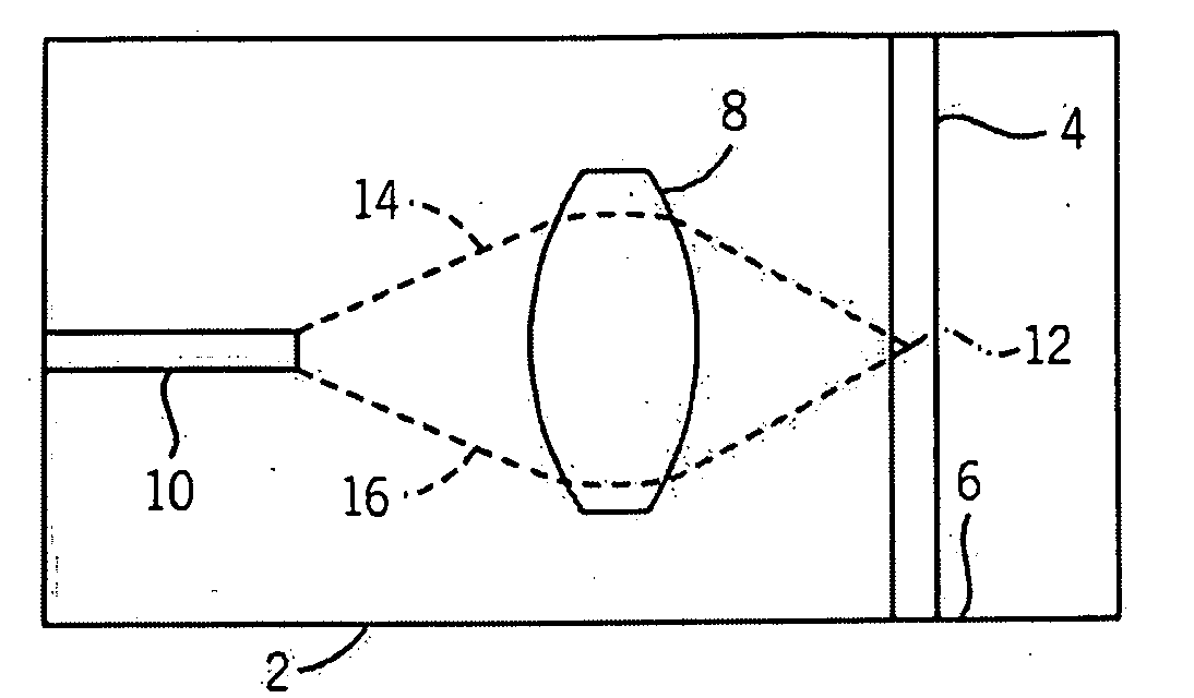
[0024]A top plan view of components 2 of an exemplary microfluidic flow cytometer are shown in schematic form. As shown, the cytometer components 2 include a microfluidic channel 4 that is capable of conducting fluids that can contain various biological materials such as blood cells or other types of cells, particles or possibly other types of materials. Fluid flow (as directed by a pump, gravity, or some other force) can proceed through the microfluidic channel 4 along a direction represented by an arrow 6, although the fluid can be directed in either direction depending upon the embodiment. Spaced apart to the side of the microfluidic channel 4 is a microfluidic lens 8, and additionally spaced apart from the lens is a waveguide 10. Thus, the lens 8 is between the microfluidic channel 4 and the waveguide 10, with the waveguide 10 extending away from the lens in a direction that also extends away from the channel.

[0025]As shown, the waveguide 10 in the present embodiment is orientat...


PUM

PropertyMeasurementUnit
Flow rateaaaaaaaaaa
Speedaaaaaaaaaa
Frequencyaaaaaaaaaa

Abstract

A flow cytometry system and related method, among other things, are disclosed. In at least one embodiment, the system includes first, second, and intermediate slab formations, the last of which has formed therewithin a microfluidic channel, a lens structure arranged proximate the microfluidic channel, and a light conveying structure arranged proximate to the lens structure. The lens structure is configured to direct a portion of light to proceed between the channel and the conveying structure. The intermediate slab formation is sandwiched between the other two slab formations. In at least another embodiment, the system includes a microfluidic prism arranged proximate to the second end of a light conveying structure. Light emanating from a microfluidic channel is provided to the conveying structure at the first end, conveyed to the second end, and provided to the prism, which outputs a plurality of portions of the light at different frequencies in different directions.

Description

CROSS-REFERENCE TO RELATED APPLICATIONS[0001]This application claims the benefit of U.S. provisional patent application No. 60 / 917,848, entitled “Light Conveying Device” filed on May 14, 2007, and further claims the benefit of U.S. provisional patent application No. 61 / 068,198, entitled “System and Method for Flow Cytometry” filed on Mar. 5, 2008, and both of the aforementioned U.S. provisional patent applications are hereby incorporated by reference herein.STATEMENT REGARDING FEDERALLY SPONSORED RESEARCH OR DEVELOPMENT[0002]This invention was made with United States Government support awarded by the following agency: Air Force Office of Scientific Research (AFOSR) Grant No. F49620-02-1-0288. The United States Government has certain rights in this invention.FIELD OF THE INVENTION[0003]The present invention relates to optical devices and, more particularly, relates to devices for conveying and / or sensing light, for example, devices that convey and sense light emissions from cells, pa...

Claims


Application Information

Patent Timeline
IPC IPC(8): G01N21/01
CPCB01L3/502776B01L2300/0654G01N15/1434B01L2400/084B01L2300/0816
Inventor GODIN, JESSICALO, YU-HWA
Owner RGT UNIV OF CALIFORNIA
Why Eureka
Try Eureka