
Waveguide illumination system

a waveguide and illumination system technology, applied in the field of light-emitting waveguides, can solve the problems of reducing system efficiency, introducing reflection losses at the mirrored surface, and light loss, and achieves the effects of efficient illumination of the underlying image, improved beam directionality, and high optical transparency and image fidelity

Active Publication Date: 2017-07-27
S V V TECH INNOVATIONS
View PDF10 Cites 66 Cited by
  • Summary
  • Abstract
  • Description
  • Claims
  • Application Information

AI Technical Summary

Benefits of technology

This patent is about a new system for extracting light from waveguides to create a controlled beam of light. The system can be used in various applications such as in a natural lighting system or in a lighting luminaire that has improved beam directionality. The system allows for controlled light extraction while minimizing light loss and controlling the angular distribution of the light. The resulting beam of light is highly optically transparent and fidelity is maintained. Overall, this technology provides a more efficient and effective way to extract light from waveguides.

Problems solved by technology

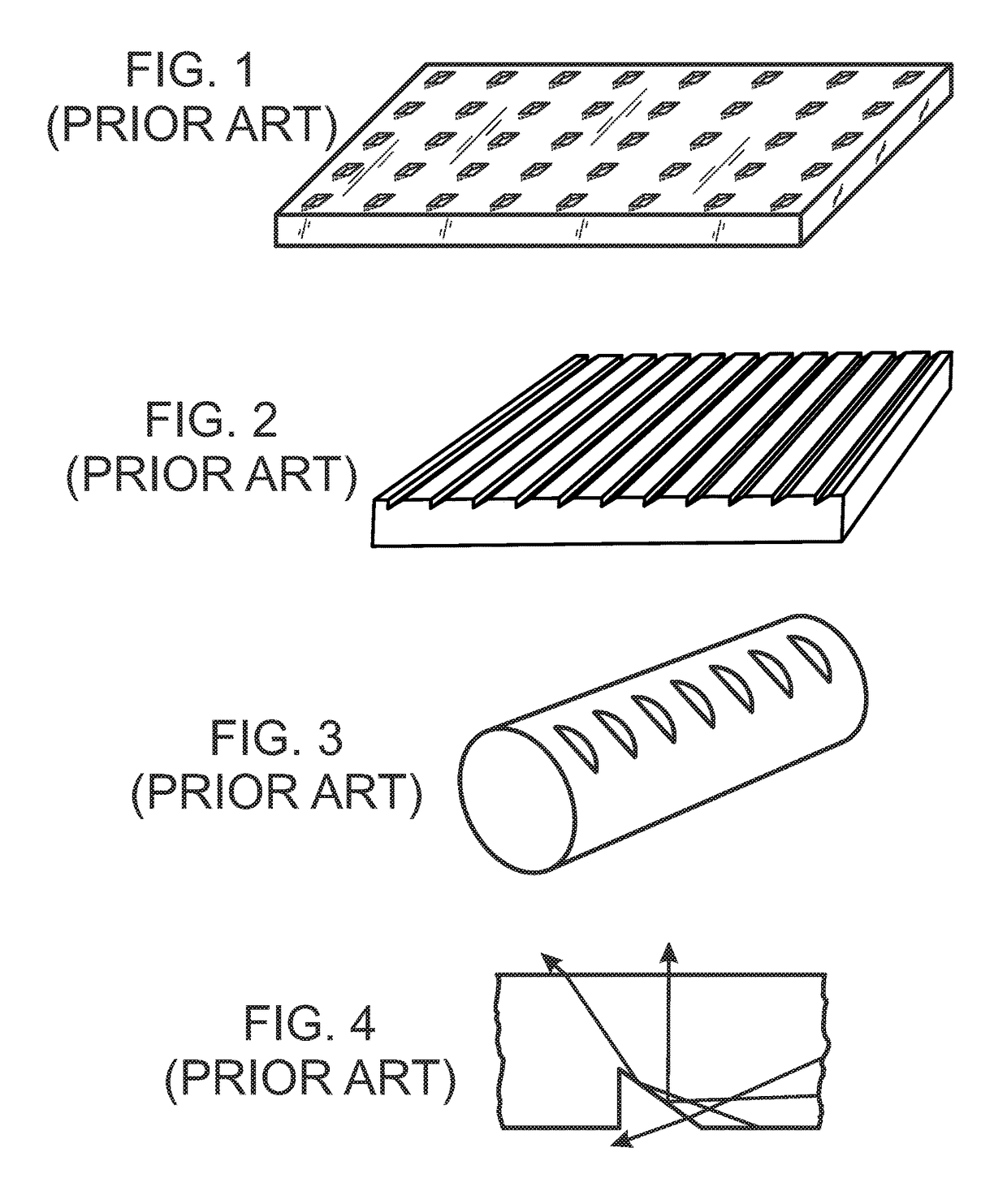
In this case, TIR will not occur and the respective rays may exit from the waveguide through the unwanted face (see FIG. 4), resulting in light loss and reduced system efficiency.
However, doing so will introduce reflection losses at the mirrored surface compared to the lossless TIR and will also add fabrication steps, such as fabricating a mask, applying the mask to the waveguide surface with precision alignment, vacuum metallization, etc.
The lack of beam directionality hampers the utility of conventional waveguide illumination systems in the applications requiring at least some degree of light collimation.
This makes the conventional devices ill suited for the front light applications in which an edge-lit lighting panel is positioned in front of a viewable screen or image print.
As a result, the visual appearance and resolution of the print may deteriorate.
Since such light has about equal chance to escape through either front or rear surface, at least a substantial portion of it will exit from the unwanted side of the waveguide resulting in energy loss and considerable glare.
The prior-art lighting panels employing light extraction features based on light scattering rather than on reflection typically introduce even more unwanted glare and light spillage due to the uncontrolled nature of light scattering mechanism.
Additionally, such lighting panels are usually characterized by a relatively high level of opacity and either substantially opaque or can be translucent at best, but not fully transparent, which inhibits the basic light guiding function of the panel.
Yet further, when the conventional planar waveguide employing light extracting features (such as surface microstructure or scattering elements) is lit from an edge, at least a portion of light extracted by these features is emitted towards the viewer which substantially degrades the contrast and visibility of the bodies or images disposed behind the waveguide.
Besides sometimes being characterized by reduced optical qualities or light spillage, the conventional systems employing relatively deep cuts, notches or grooves may also be affected by at least some loss of structural strength and rigidity compared to a smooth-surface panel having no such microstructures.

Method used


Image

  • Waveguide illumination system
  • Waveguide illumination system
  • Waveguide illumination system

Examples


Embodiment Construction

[0078]Referring more specifically to the drawings, for illustrative purposes the present invention is embodied in the apparatus generally shown in the preceding figures. It will be appreciated that the apparatus may vary as to configuration and as to details of the parts without departing from the basic concepts as disclosed herein. Furthermore, elements represented in one embodiment as taught herein are applicable without limitation to other embodiments taught herein, and in combination with those embodiments and what is known in the art.

[0079]A wide range of applications exist for the present invention in relation to the collection of electromagnetic radiant energy, such as light, in a broad spectrum or any suitable spectral bands or domains. Therefore, for the sake of simplicity of expression, without limiting generality of this invention, the term “light” will be used herein although the general terms “electromagnetic energy”, “electromagnetic radiation”, “radiant energy” or exe...


PUM


Abstract

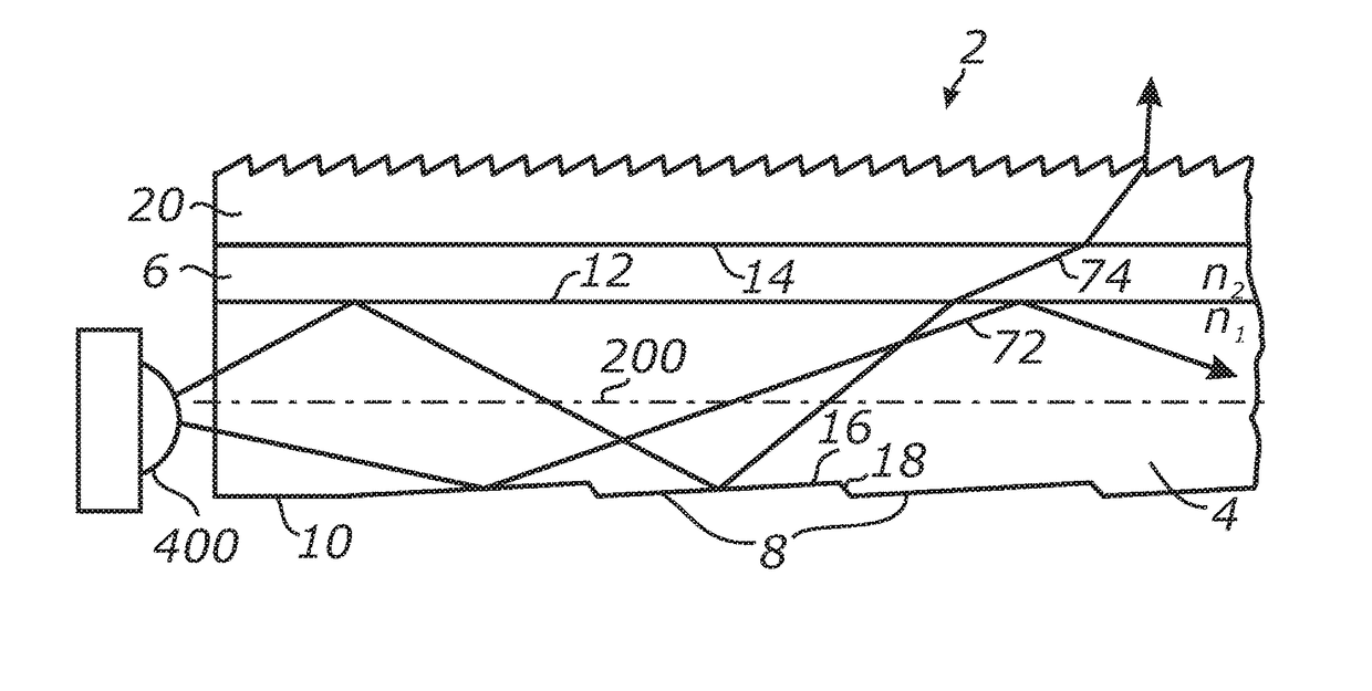
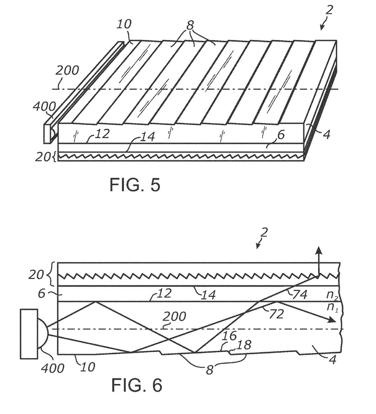
An illumination system employing a waveguide that receives and propagates light in response to transmission and total internal reflection. Light deflecting elements distributed along the propagation path incrementally change the out-of-plane angles of light rays and cause decoupling of portions of light from the waveguide at different distances from the light input edge or end. Light may escape from the waveguide into an intermediate layer at low out-of-plane angles and can be further redirected by light extraction features out of the system. In one embodiment, the illumination system is configured to emit collimated light. In one embodiment, the illumination system includes shallow surface relief features. In one embodiment, the light deflecting elements include forward-scattering particles distributed throughout the volume of the waveguide.

Description

CROSS-REFERENCE TO RELATED APPLICATIONS[0001]This application is a continuation of application Ser. No. 13 / 682,004 filed on Nov. 20, 2012. This application also claims priority from U.S. provisional application Ser. No. 61 / 563,018 filed on Nov. 22, 2011, incorporated herein by reference in its entirety, and from U.S. provisional application Ser. No. 61 / 648,236 filed on May 17, 2012, incorporated herein by reference in its entirety.STATEMENT REGARDING FEDERALLY SPONSORED RESEARCH OR DEVELOPMENT[0002]Not ApplicableINCORPORATION-BY-REFERENCE OF MATERIAL SUBMITTED ON A COMPACT DISC[0003]Not ApplicableNOTICE OF MATERIAL SUBJECT TO COPYRIGHT PROTECTION[0004]A portion of the material in this patent document is subject to copyright protection under the copyright laws of the United States and of other countries. The owner of the copyright rights has no objection to the facsimile reproduction by anyone of the patent document or the patent disclosure, as it appears in the United States Patent ...

Claims


Application Information

Patent Timeline
Patent Type & Authority Applications(United States)
IPC IPC(8): F21V8/00
CPCG02B6/0045G02B6/0085G02B6/0055G02B6/005G02B6/001G02B6/0038G02B6/0041G02B6/0043G02B6/0053G02B6/0061G02B6/0065F21S43/26231F21S10/005
Inventor VASYLYEV, SERGIY
Owner S V V TECH INNOVATIONS
Learn More