Filter based multiplexer/demultiplexer component

a filter-based multiplexer and component technology, applied in multiplex communication, instruments, other domestic objects, etc., can solve the problems of large insertion loss, large manufacturing cost, difficult fabrication, etc., and achieve the effect of reducing insertion loss, reducing insertion loss, and requiring little alignment tim

Inactive Publication Date: 2005-03-22
LUMENTUM FIBER OPTICS INC
View PDF11 Cites 81 Cited by
  • Summary
  • Abstract
  • Description
  • Claims
  • Application Information

AI Technical Summary

Benefits of technology

In accordance with the present invention, an optical multiplexer or demultiplexer system is disclosed which is significantly easier to assemble, requires little time in alignment, and reduces insertion loss. The system includes a pre-formed lens block arranged with

Problems solved by technology

However, in order to effectively utilize the bandwidth of the optical fiber, optical signals must be multiplexed and demultiplexed onto the fiber.
These systems are difficult to fabricate, have large insertion losses, and are only applicable to single-mode fibers.
The major problem with such devices is that they often include bulky and costly lenses and such which are very hard to reliably align, leading to large manufacturing costs and a bulky final product.
However, the difficulty in assembling and aligning demultiplexer 10 is great, which increases the manufacturing cost because of time spent in active alignment of components.
It is difficult to design the waveguide for both a multimode and single mode fiber input in such a way that the

Method used


Image

  • Filter based multiplexer/demultiplexer component
  • Filter based multiplexer/demultiplexer component
  • Filter based multiplexer/demultiplexer component

Examples


Embodiment Construction

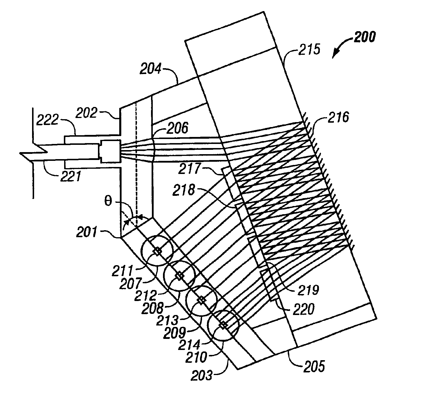
FIG. 2A shows a component 200 according to the present invention. Component 200 can be a multiplexer or a demultiplexer and includes a lens block 201 and a mirror-filter block 215. Each of lens block 201 and mirror-filter block 215 can be molded as a separate piece or, alternatively, lens block 201 and mirror-filter block 215 can be molded as a single piece. The only alignment required at assembly is the relative alignment between lens block 201 and mirror-filter block 215 and the placement of optical filters 217 through 220 and optical devices 211 through 214.

Lens block 201 includes a collimating portion 202 and a lens-array portion 203 formed from a material that is transparent at the wavelengths of light transmitted on optical fiber 221. Collimating portion 202 includes placement for a collimating lens 206 so that light transmitted from optical fiber 221 is collimated, if component 200 is a demultiplexer. Collimating lens 206 couples light between optical fiber 221 and lens block...


PUM


Abstract

A multiplexer/demultiplexer optical system component that is passively aligned upon assembly is disclosed. The optical system includes a lens block and a mirror-filter block. In some embodiments, optical filters are positioned and epoxyed to the mirror-filter block using a positioning tool. In some embodiments, optical filters are positioned and epoxyed on a support structure which has been etched to receive the optical filters. The mirror-filter block is a block having flat surfaces, one of which is a flat reflecting surface. The lens block is formed by injection molding and includes a barrel for holding and positioning an optical fiber, placement for a collimating lens, and placements for focusing lenses such that, when assembled, light incident on each of the focusing lenses propagates along the optical axis of the focusing lens. In some embodiments, the collimating lens and the focusing lenses are integrally formed with the lens block. In some embodiments, one or more of the collimating lens or focusing lenses are formed separately and inserted into holders integrally formed with the lens block to receive the lens. In some embodiments, the lens block includes a reflecting surfaces that directs light onto the focusing lenses. Assembly and alignment of the multiplexer/demultiplexer involves positioning a flat surface of the mirror-filter block against a receiving surface of the lens block with the filters between them and epoxying the components in place.

Description

BACKGROUND1. Field of the InventionThe present invention relates to a multiplexer or demultiplexer optical component and, in particular, to a multiplexer or demultiplexer for a wavelength division multiplexed optical system.2. Discussion of Related ArtWavelength division multiplexing has become a standard in optical networks over the last few decades. Wavelength division multiplexing (WDM) exploits the potential bandwidth of optical fibers by transmitting data over several channels on the same fiber. Each channel is transmitted on the optical fiber at a different wavelength. The rate of data transmission over the fiber, then, can be increased by a factor of M, where M is the number of channels (i.e., the number of different wavelengths) being transmitted over the fiber.Recently, an explosion of WDM technologies has appeared on the market. Systems having 8, 16, and 32 channels have become commonplace. Dense WDM, DWDM, for example, has 32 channels following an ITU grid with 0.8 nm wav...

Claims


Application Information

Patent Timeline
IPC IPC(8): G02B6/32G02B6/42G02B6/34
CPCG02B6/29367G02B6/2938G02B6/4292G02B6/32G02B6/4206
Inventor CHEN, YEOU-YENVANNIASINKAM, JOSEPHMEYER, JONCARROLL, CHRISWAI, JOSEPHVIRAY, CHRISTOPHERREYSEN, BILLTWU, BOR-LONG
Owner LUMENTUM FIBER OPTICS INC
Why Eureka
Try Eureka