
Protective case for electronic devices

a protective case and electronic technology, applied in the direction of electrical apparatus casings/cabinets/drawers, electrical apparatus construction details, instruments, etc., can solve the problems of easy absorption of surface abrasion, inconvenience in portability, and aesthetics still annoying to most people, so as to prevent the surface of the electronic mobile communication device case from being scratched, reduce the burden of carrying, and reduce the weight

Inactive Publication Date: 2012-07-19
ESOTERISM
View PDF3 Cites 55 Cited by
  • Summary
  • Abstract
  • Description
  • Claims
  • Application Information

AI Technical Summary

Benefits of technology

"The present invention provides a protective case for electronic mobile communication devices that prevents scratches and damage to the device. The case is made up of two frames that are designed to fit snugly around the device, with positioning devices that keep it secure. The frames have rounded corners to prevent abrasions and scratches when placed on a desktop. The case is also lighter than traditional leather cases, making it easier to carry. The manufacturing process of the case is cost-effective compared to conventional methods. Overall, the protective case provides a safe and secure way to carry and protect electronic mobile communication devices."

Problems solved by technology

However, in use, its surface may be easily abraded by the desktop or normal usage; although this usually will not affect the functions of the electronic mobile communication devices priced probably up to hundreds or thousands of dollars, such abrasions are still annoying to most in terms of aesthetics.
But its drawbacks may include increased weight and volume for carrying by hand, accordingly causing inconvenience in portability.
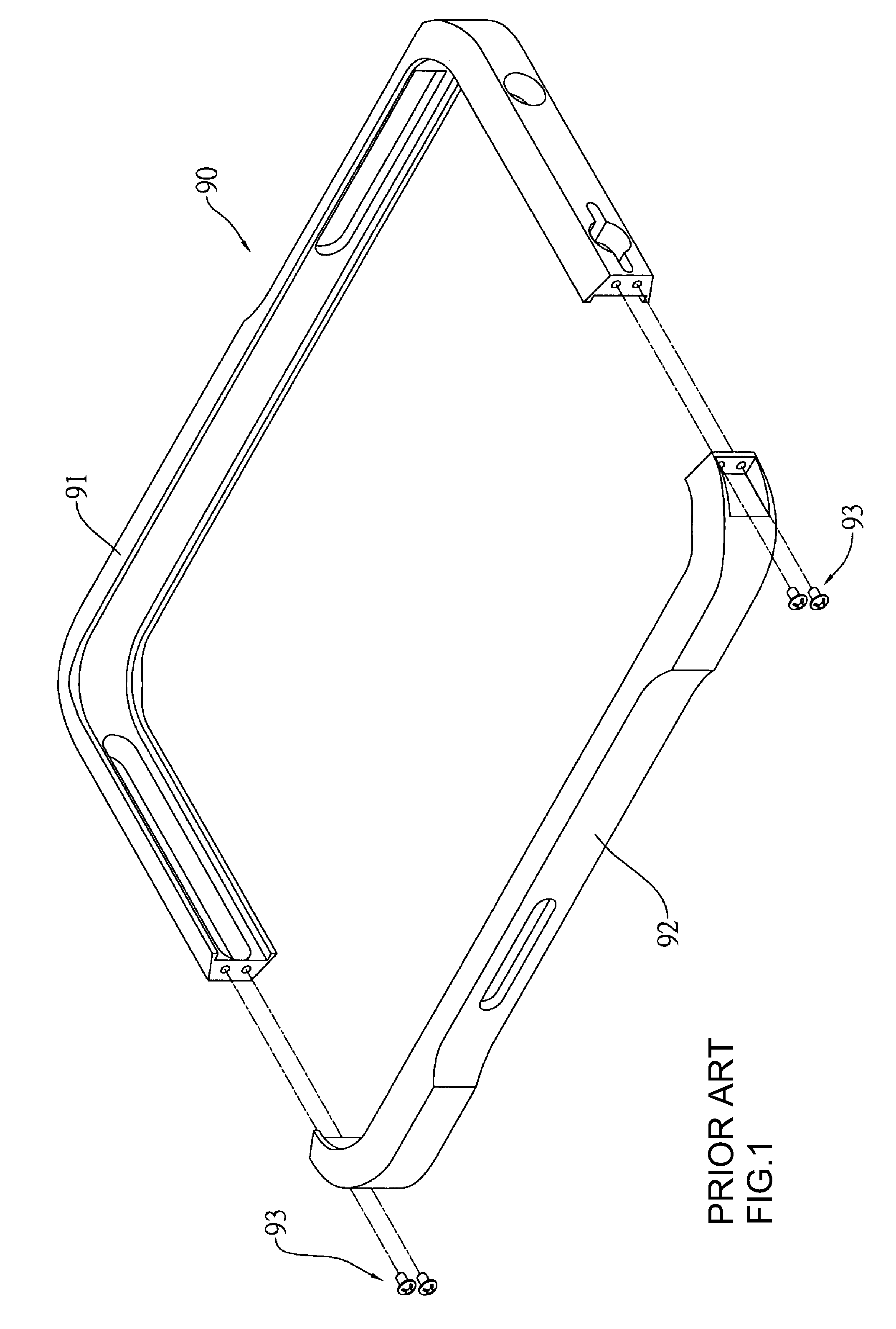
Furthermore, based on currently available manufacture processes, after formation of the “Π”-shaped stick 91, its opening may slightly shrink inward which may lead to even greater abrasions on the electronic mobile communication device slithering therein thus undesirably resulting in deeper scratches on the case of the electronic mobile communication device.

Method used


Image

  • Protective case for electronic devices
  • Protective case for electronic devices
  • Protective case for electronic devices

Examples


Embodiment Construction

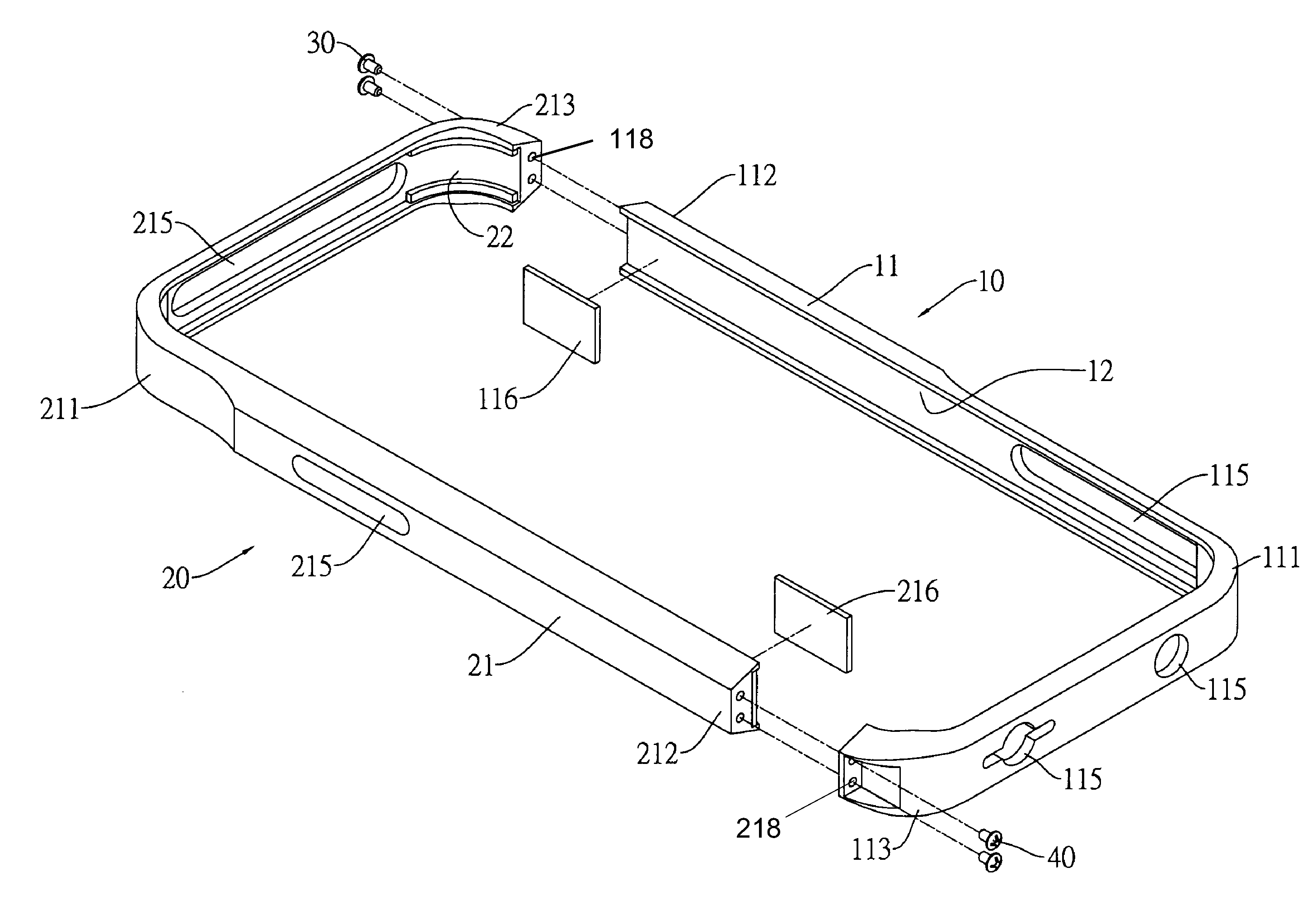
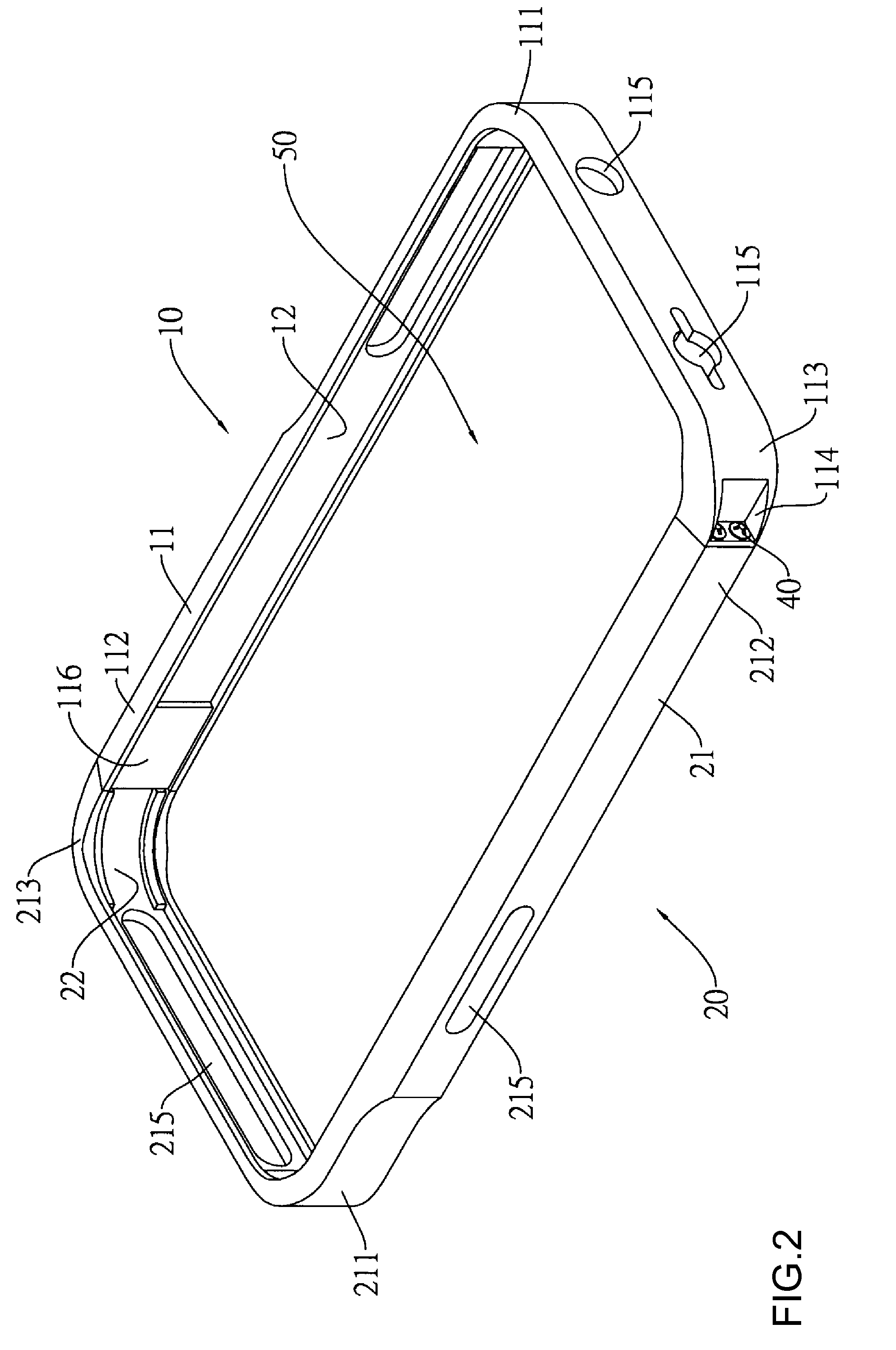
[0024]Referring now to FIGS. 2 and 3, a perspective view and an assembly view of a protective case for electronic mobile communication devices in accordance with the invention are respectively shown.

[0025]The protective case for electronic mobile communication devices comprises a first frame 10 and a second frame 20. The first frame 10 includes a first stick body 11 and a first positioning device 12, in which the first stick body 11 is configured with a rounded corner 111 and the two ends of the first stick body 11 are respectively defined as a first end 112 and a second end 113. The first positioning device 12 is configured along the inner side of the first stick body 11, with both ends being respectively located at the first end 112 and the second end 113. The second frame 20 includes a second stick body 21 and a second positioning device 22, in which the second stick body 21 is configured with a rounded corner 211 and the two ends of the second stick body 21 are respectively defi...


PUM


Abstract

The present invention provides a protective case for electronic mobile communication devices in which nips an electronic device in position through an accommodation space formed by combining a first frame with a second frame. When combining the electronic mobile communication device with the protective case according to the invention, the electronic mobile communication device is only required to lean against the first frame and the second frame, and no scratches occur during the combination. Meanwhile, when the device in combination with the invention is placed on a desktop, the electronic mobile communication device can be kept at a distance from the desktop, thereby protecting the surface of the electronic device from being abraded by the desktop.

Description

BACKGROUND OF THE INVENTION[0001]1. Field of the Invention[0002]The present invention relates to a protective case for electronic mobile communication devices; in particular, it relates to a protective case for encapsulating the edge of the electronic mobile communication device.[0003]2. Description of Related Art[0004]Thanks to convenience brought by touch screens, the keyboard of various portable electronic mobile communication devices now can be replaced so that such portable electronic mobile communication devices become thinner and slimmer and can be easily carried; examples thereof can be found in currently very popular touch panel notebook computers or touch screen mobile phones and mobile communication devices.[0005]However, in use, its surface may be easily abraded by the desktop or normal usage; although this usually will not affect the functions of the electronic mobile communication devices priced probably up to hundreds or thousands of dollars, such abrasions are still ...

Claims


Application Information

Patent Timeline
Patent Type & Authority Applications(United States)
IPC IPC(8): H05K7/00
CPCA45F5/10H04M1/04
Inventor WU, DA-CHUNGLEE, WEI-CHIEH
Owner ESOTERISM
Learn More