Surface light source device of side light type

a technology of surface light source and side light, which is applied in the direction of lighting and heating equipment, instruments, machines/engines, etc., can solve the problems of unsatisfactory bright lines along both sides, and achieve the effect of preventing the generation of bright lines along the side edges of the emission surfa

Inactive Publication Date: 2002-06-18
ENPLAS CORP +1
View PDF10 Cites 57 Cited by
  • Summary
  • Abstract
  • Description
  • Claims
  • Application Information

AI Technical Summary

Benefits of technology

The present invention aims to solve the abovementioned problems of the conventional surface light source device of side light type. It is an object of the present invention to prevent generation of bright lines along side edges of the emission surface in a surface light source device of side light type. Described from another point of view, the present invention aims to enable generation of bright lines along side edges of the emission surface to be prevented even when the surface light source device of said type employs a guide plate having an emission surface which comprises a light control surface.
The projections, provided on the back face of the guide plate in a region along the edge, diversify and spread the propagation direction of illuminating light, arriving from the emission surface of the guide plate and the side face edge, and light arriving from a frame, which forms a peripheral member. Consequently, light arising from such illumination of the edge or the frame is prevented from being strongly emitted locally from the emission surface thereafter. As a result, generation of bright lines along the side edges of the emission surface is prevented. Bright lines of this type are especially liable to occur when a prism surface is provided on the emission surface, but they can be effectively controlled by the application of the present invention.

Problems solved by technology

However, in the conventional device described above, undesirable bright lines are generated along both side edges on the emission surface 2C (left and right belt regions as viewed from the primary light source 3).

Method used


Image

  • Surface light source device of side light type
  • Surface light source device of side light type
  • Surface light source device of side light type

Examples


Embodiment Construction

(1) Embodiment

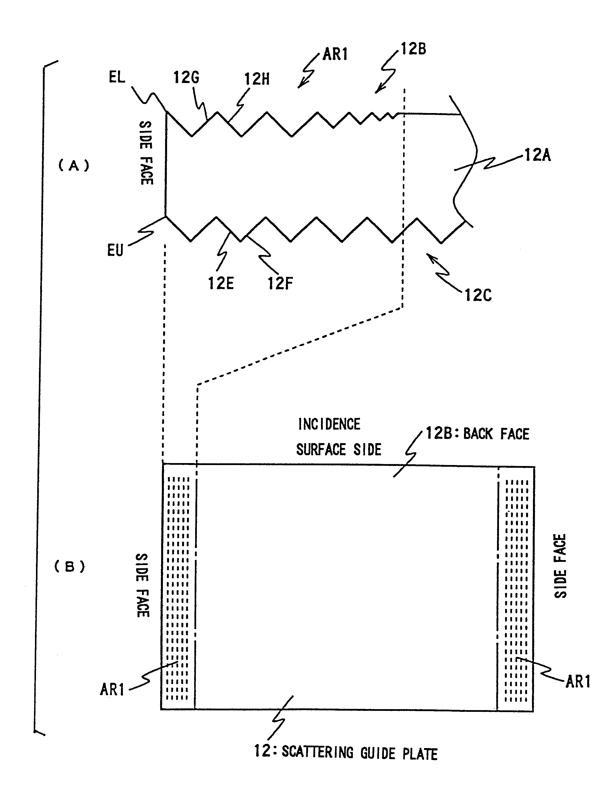
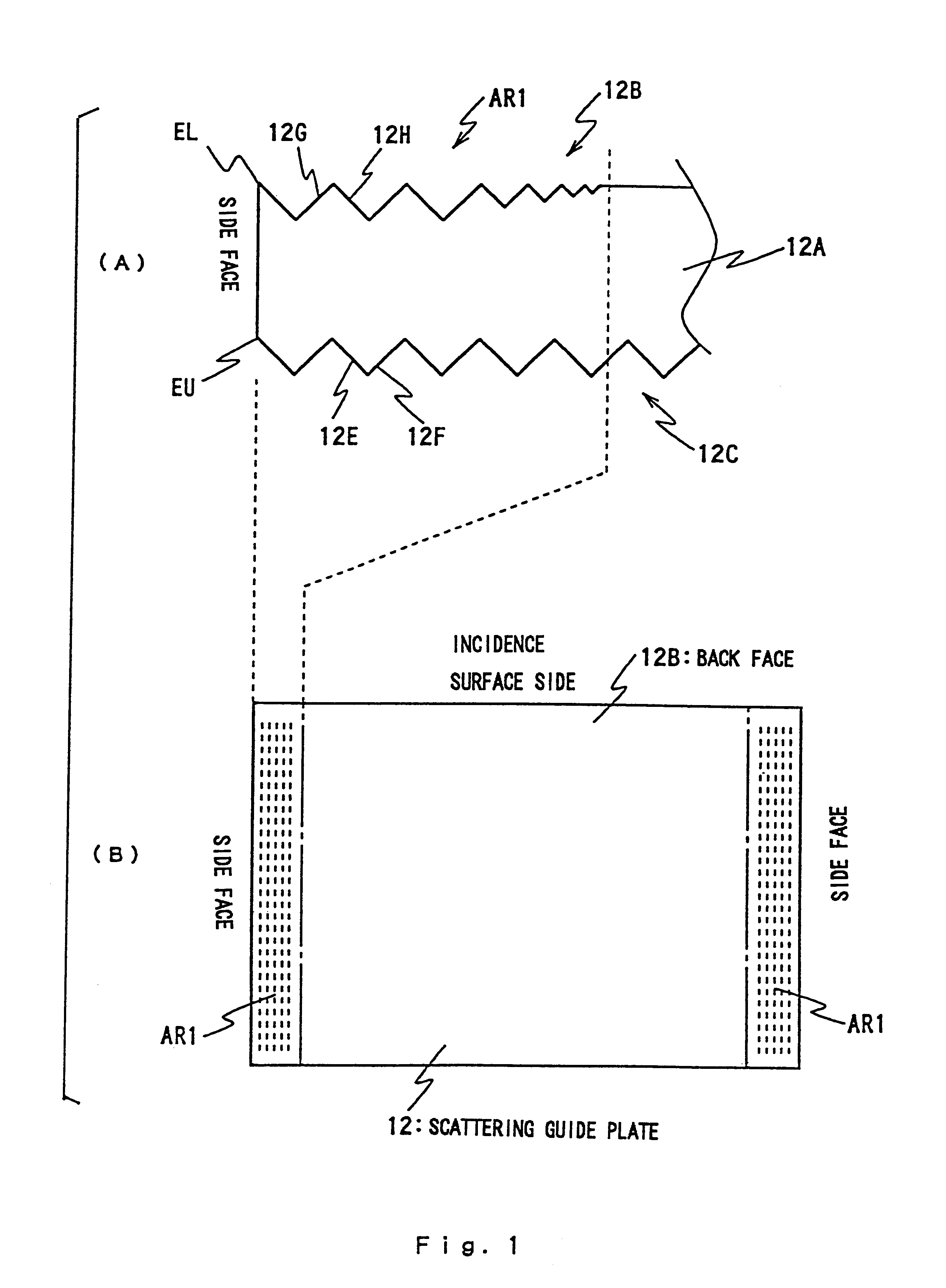
FIG. 1 illustrates features of a scattering guide plate 12 used in the present invention, showing a plan view (A) of under surface 12B and a side view (B) from an incidence surface (incidence end surface) 12A. The surface light source device of side light type according to the present invention replaces the guide plate 2 of the device shown in FIG. 8 and FIG. 9 with a new scattering guide plate 12.

The following explanation centers on structure and effect of the scattering guide plate 12, with reference to FIG. 8 and FIG. 9 as necessary. In FIG. 8 and FIG. 9, reference symbols relating to the scattering guide plate 12 are indicated in brackets.

As shown in FIG. 1, the scattering guide plate 12 (hereinafter, guide plate 12), which is generally wedge-shaped, preferably comprise the same type of material as the scattering guide body 2 (see FIG. 8 and FIG. 9). The matrix comprises, for instance, polymethyl-methacrylate (PMMA) and a great number of light-permeable particles, ...


PUM

PropertyMeasurementUnit
angleaaaaaaaaaa
critical angleaaaaaaaaaa
top angleaaaaaaaaaa

Abstract

Illuminating light, supplied from a primary light source of a surface light source device of side light type, passes through an incidence surface (12A) and enters a wedge-shaped scattering guide plate (12). Inside the guide plate (12), the illuminating light propagates toward the end while being repeatedly reflected between a back face (12B) and an emission surface (12C). During this process, the illuminating light receives scattering action of particles or the like in the guide plate (12). The emission surface (12C) provides a prism surface. The back face (12B) comprises a plurality of projections in a belt region (AR1) along an edge (EL). The projections run generally parallel to the edge (EL) and each has a pair of slopes (12G and 12H). The height of the projections (that is, depth of the troughs) or the inclination of the slopes (12G and 12H) preferably decrease according to distance from the edge (EL). The projections diffuse light propagation direction, thereby preventing generation of bright lines around the edge (EU) of the emission surface.

Description

The present invention relates to a surface light source device of side light type, and more particularly to a technique for improving quality of illuminating light in the device. The surface light source device according to the present invention is applied to, for instance, backlighting of a liquid crystal display.RELATED ARTIt is well known that a surface light source device of side light type is applied to backlighting of a liquid crystal display. The surface light source device supplies illuminating light from the back face of a liquid crystal panel. This arrangement is suitable for making the overall shape of the display thinner.In general, a surface light source device of side light type uses a rod-shaped light source, such as a cold cathode tube, as a primary light source. The rod-shaped light source is provided on a side of a guide plate (plate-like guide body). Illuminating light, emitted from the primary light source, is guided inside the guide plate through an incidence en...

Claims


Application Information

Patent Timeline
Patent Type & Authority Patents(United States)
IPC IPC(8): F21V8/00F21V5/00F21V5/02G02B6/00G02F1/1335G02F1/13357
CPCG02B6/0061G02B6/0038F21V5/02G02B6/0036
Inventor OHKAWA, SHINGO
Owner ENPLAS CORP
Why Eureka
Try Eureka