Midsole Structure for an Athletic Shoe
- Summary
- Abstract
- Description
- Claims
- Application Information
AI Technical Summary
Benefits of technology
Problems solved by technology
Method used
Image

Examples
first embodiment
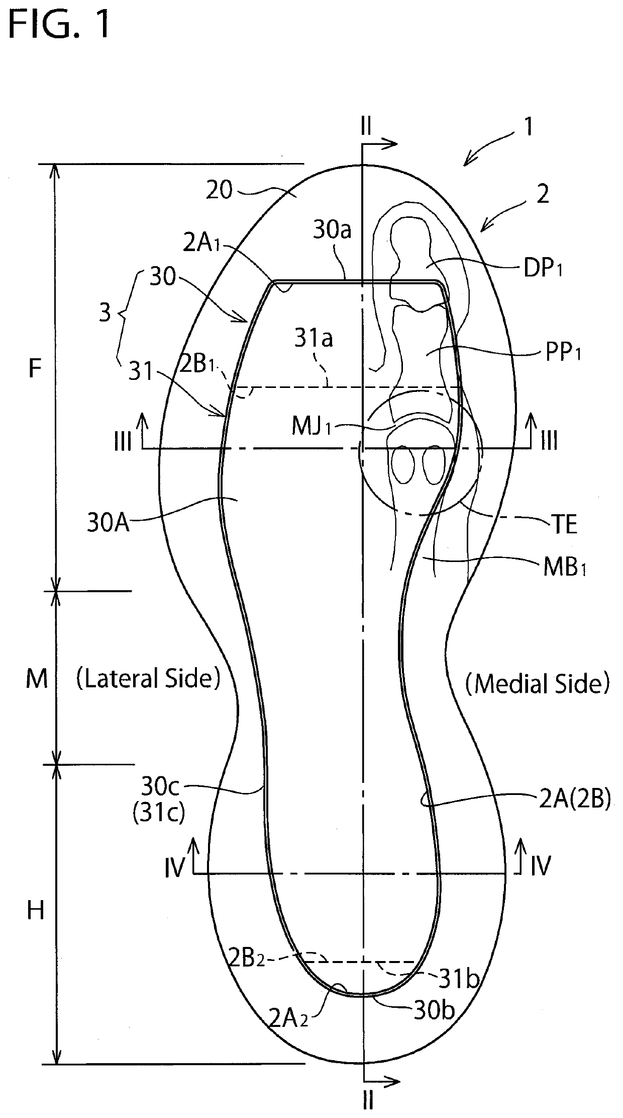
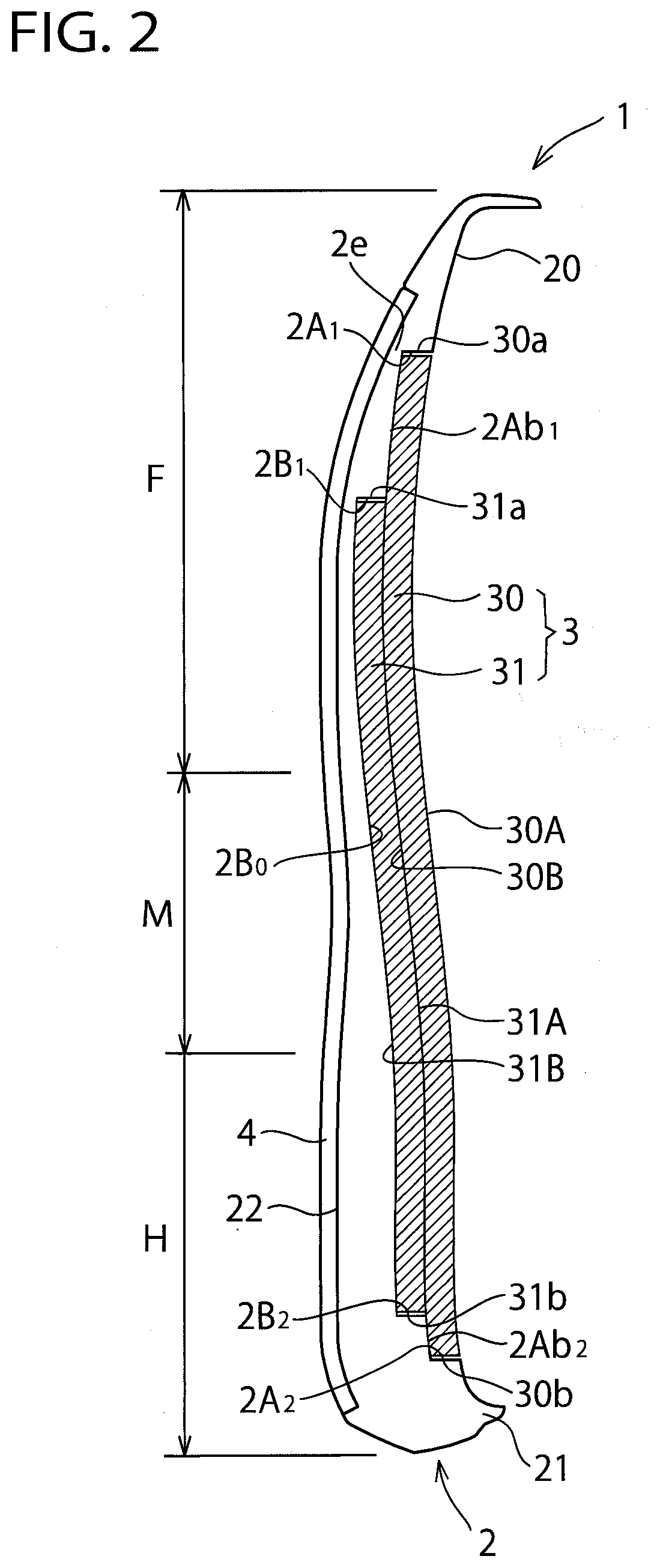
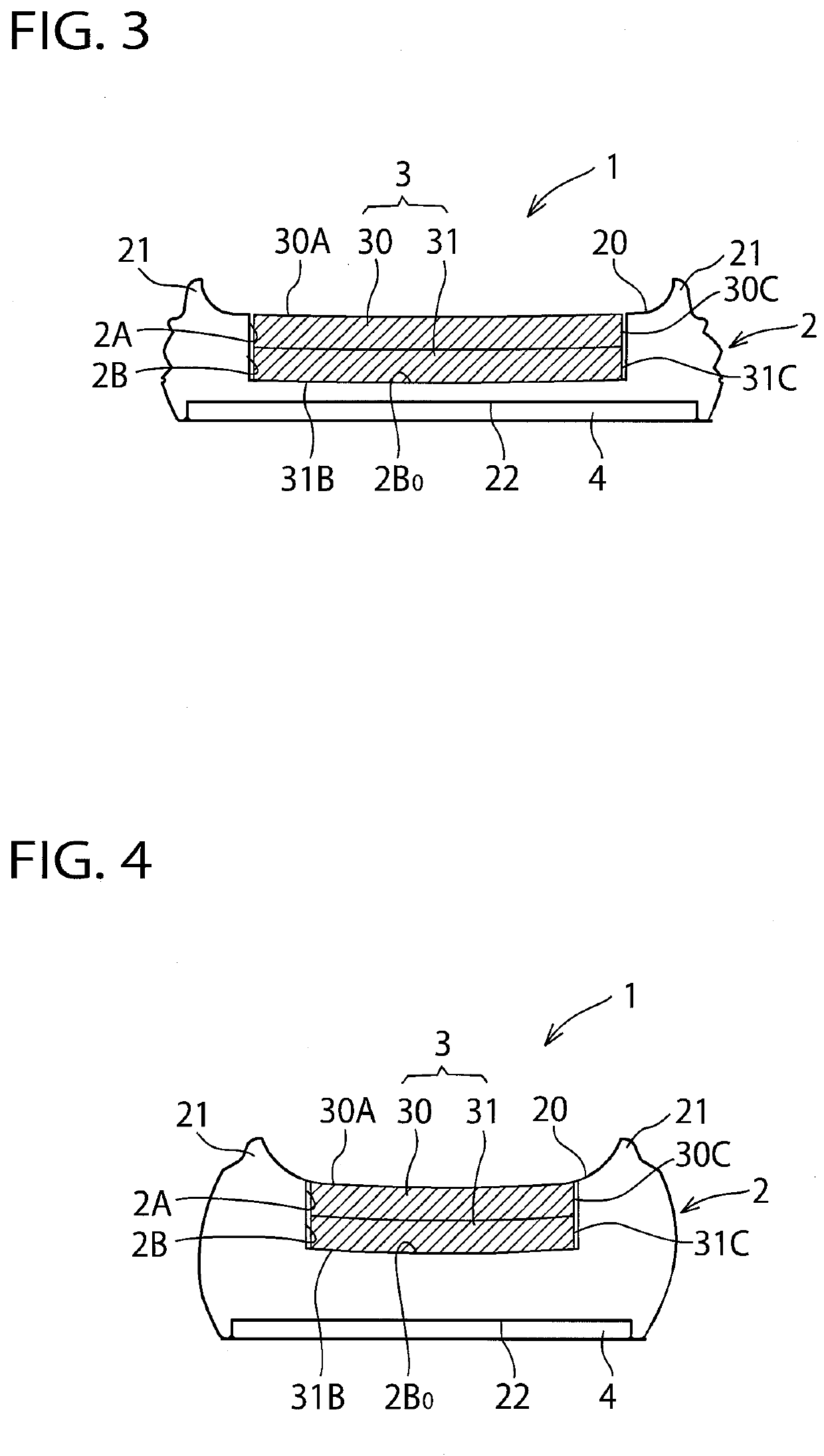
[0060]FIGS. 1 to 4 show a midsole structure for an athletic shoe according to a first embodiment of the present invention. As shown in FIGS. 1 and 2, the midsole structure 1 includes a midsole body 2 extending from the heel region H through the midfoot region M to the forefoot region H and a sheet composite (see hatched portions) 3 extending from the heel region H through the midfoot region M to the forefoot region H on a side of an upper surface (i.e. a foot-sole-contact-side surface) 20 of the midsole body 2. On a lower surface (i.e. a ground-contact-side surface) 22 of the midsole body 2, an outsole 4 is fixedly attached that has a ground-contact surface that contacts the ground. As shown in FIGS. 2 to 4, the midsole body 2 has an upraised portion 21 that extends upwardly from an outer circumferential edge portion of the upper surface 20. A bottom portion of an upper (not shown) of the shoe is to be fixedly attached to the upraised portion 21. In such a manner, the athletic shoe ...
second embodiment
[0091]FIGS. 5 to 8 show a midsole structure for an athletic shoe according to a second embodiment of the present invention. In these drawings, like reference numbers indicate identical or functionally similar elements to those in the first embodiment. In the first embodiment, an example was shown in which the concave portions 2A, 2B that house the sheet composite 3 are formed on the upper surface (i.e. the foot-sole-contact-side surface) 20 of the midsole body 2. In this second embodiment, the concave portions 2A, 2B that house the sheet composite 3 are formed on the lower surface (i.e. the ground-contact-side surface) 22 of the midsole body 2.
[0092]That is, the concave portion 2B disposed below is open to the lower surface 22 and the concave portion 2A disposed above is open to the lower surface 22 through the concave portion 2B. Neither of the concave portions 2A, 2B are not open to the upper surface 20.
[0093]Also, generally longitudinal lengths of the upper sheet 30 and the lower...
third embodiment
[0098]FIGS. 9 to 12 show a midsole structure for an athletic shoe according to a third embodiment of the present invention. In these drawings, like reference numbers indicate identical or functionally similar elements to those in the first and second embodiments. In the first embodiment, an example was shown in which the concave portions 2A, 2B that house the sheet composite 3 is open to the upper surface 20 and is not open to the lower surface 22 of the midsole body 2, and in the second embodiment, an example was shown in which the concave portions 2A, 2B is open to the lower surface 22 and is not open to the upper surface 20 of the midsole body 2.
[0099]In this third embodiment, the concave portions 2A and 2B are open to both of the upper and lower surfaces 20, 22 of the midsole body 3. Also, in this third embodiment, the lower sheets 31, 31′ composing the sheet composite 2 do not extend from the heel region H through the midfoot region M to the forefoot region F. The lower sheets ...
PUM
| Property | Measurement | Unit |
|---|---|---|
| Thickness | aaaaa | aaaaa |
| Structure | aaaaa | aaaaa |
Abstract
Description
Claims
Application Information
 - R&D
- Intellectual Property
- Life Sciences
- Materials
- Tech Scout
- Unparalleled Data Quality
- Higher Quality Content
- 60% Fewer Hallucinations
Browse by: Latest US Patents, China's latest patents, Technical Efficacy Thesaurus, Application Domain, Technology Topic, Popular Technical Reports.
© 2025 PatSnap. All rights reserved.Legal|Privacy policy|Modern Slavery Act Transparency Statement|Sitemap|About US| Contact US: help@patsnap.com