
Eureka
For R&D, Eureka makes reading and utilizing patents & technical documents easy.
Eureka AIR
Designed for self-driven R&D workflows. Generate viable solutions, solve complex R&D challenges, empower your innovation with AI.

Eureka Materials
Designed for material experts only. Revolutionize your material R&D, from search, analyze, to developing new materials.

TechResearch
Generate reliable direction feasibility study reports for your R&D in just a few steps.

TechSeek
Discover and master advanced knowledge NOW. Basics, ideas, possibilities, all at once.

TechMind
As an expert in R&D Theories, TechMind can generates customized viable solutions instantly.

TechRisk
Analyze your overall solution with one click, know your potential R&D risks in advance.

TechMonitor
Get weekly tech updates, stay abreast of the latest tech innovations and key insights.
Method and system of manufacturing armature coil
- Summary
- Abstract
- Description
- Claims
- Application Information
AI Technical Summary
Benefits of technology
Problems solved by technology
Method used
Image

Examples
first embodiment
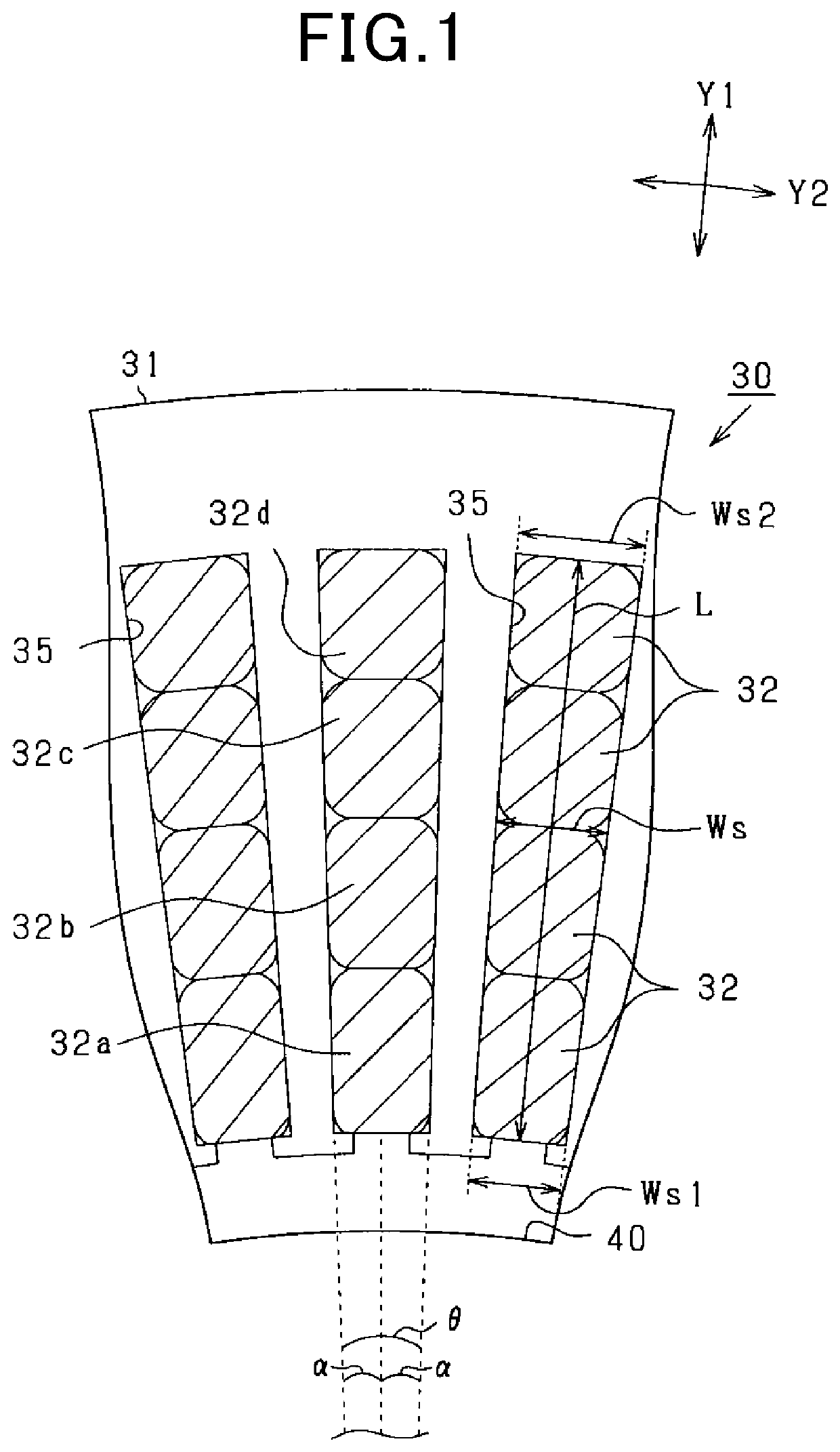
[0023]Referring now to the drawings, wherein like reference numerals designate identical or corresponding parts throughout the several views thereof, and to FIG. 1, a partial cross-sectional view illustrating a stator (i.e., an armature) including multiple stator coils (i.e., armature coils) prepared according to the present disclosure is described.
[0024]Specifically, the stator 30 has a hollow cylindrical stator core 31 (i.e., an armature core) and multiple stator coils 32 (i.e., armature coils) installed in the stator core 31. Herein below, a radial direction represents that of the stator core 31 as shown by arrow Y1 in applicable drawings. Also, a circumferential direction represents that of the stator core 31 as indicated by arrow Y2 in applicable drawings.
[0025]Further, as shown in FIG. 1, in the stator core 31, multiple slots 35 (i.e., multiple stator slots) are formed at a given interval in the circumferential direction thereof. The stator coils 32 are installed (disposed) in...
second embodiment
[0070]Now, the present disclosure is described with reference to FIGS. 5A to 6B. In the second embodiment, the die used in the first embodiment is modified as will be described herein below in detail.
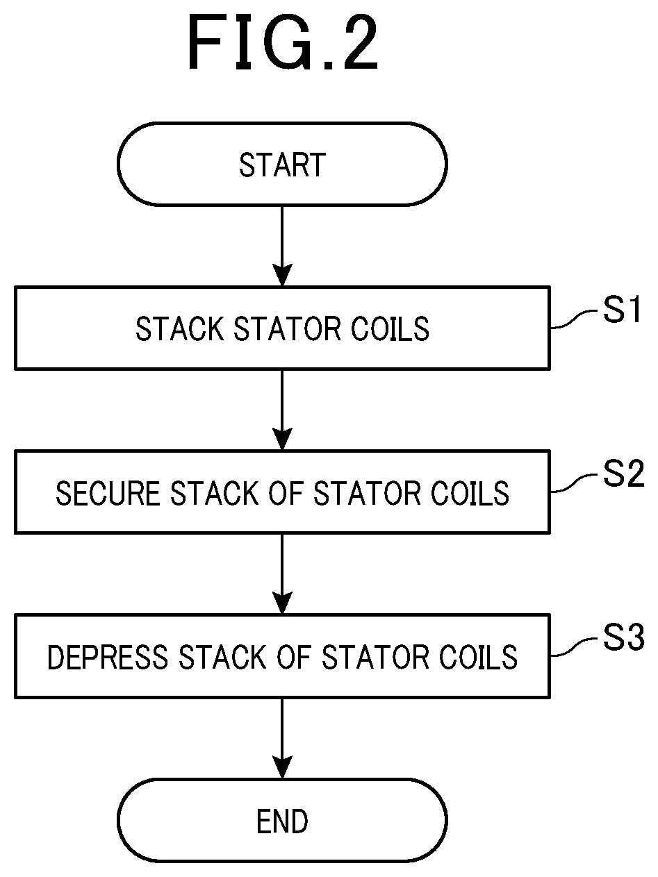
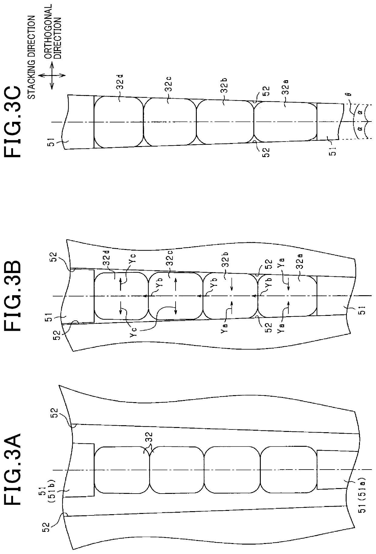
[0071]First, in a first step (i.e., in step S1 (see FIG. 2)) of the second embodiment, four stator coils 32 are stacked in a horizontal direction (i.e., placed side by side (herein below the same)) as shown in FIG. 5A and FIG. 6A. That is, a longitudinal direction of a stack of stator coils 32 aligns with the horizontal direction. In the first step, the stator coils 32 are stacked such that neighboring planes of the stator coils 32 contact each other.
[0072]Here, as shown in FIG. 6A, in the second embodiment, a width of the stack of stator coils 32 before molding in an orthogonal direction (i.e., a vertical direction) is herein below referred to as Wa. Further, a total thickness in the stacking direction (i.e., in a left and right direction) of the stack of stator coils 32 before molding...
PUM
| Property | Measurement | Unit |
|---|---|---|
| Width | aaaaa | aaaaa |
Abstract
Description
Claims
Application Information
 - R&D Engineer
- R&D Manager
- IP Professional
- Industry Leading Data Capabilities
- Powerful AI technology
- Patent DNA Extraction
Browse by: Latest US Patents, China's latest patents, Technical Efficacy Thesaurus, Application Domain, Technology Topic, Popular Technical Reports.
© 2024 PatSnap. All rights reserved.Legal|Privacy policy|Modern Slavery Act Transparency Statement|Sitemap|About US| Contact US: help@patsnap.com