Unlock instant, AI-driven research and patent intelligence for your innovation.

Power conversion apparatus

a technology of power conversion apparatus and short-circuit current, which is applied in the direction of dc-ac conversion without reversal, power conversion system, electrical apparatus, etc., can solve the problems of difficult to secure failure tolerance, or the tolerance with respect to the short-circuit current of the power conversion apparatus, and achieve the effect of easy to secure toleran

Active Publication Date: 2021-01-21
FUJI ELECTRIC CO LTD
View PDF0 Cites 0 Cited by
  • Summary
  • Abstract
  • Description
  • Claims
  • Application Information

AI Technical Summary

Benefits of technology

The objective of this patent is to create a power conversion system that can easily handle short-circuit currents without being affected.

Problems solved by technology

For this reason, the short-circuit current flowing to the switching element forming the lower arm of the semiconductor module becomes unbalanced among the plurality of semiconductor modules, to thereby make it difficult to secure failure tolerance, or tolerance with respect to the short-circuit current of the power conversion apparatus.
Similarly, it is difficult to secure the failure tolerance, or the tolerance with respect to the short-circuit current of the power conversion apparatus, when the switching element forming the lower arm is short-circuited due to a failure or the like.

Method used


Image

  • Power conversion apparatus
  • Power conversion apparatus
  • Power conversion apparatus

Examples


first embodiment

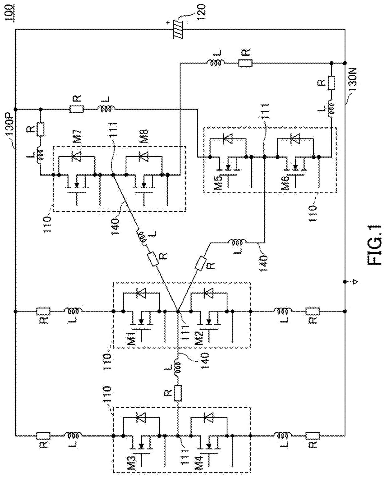
[0021]FIG. 1 is a diagram illustrating a circuit configuration of a power conversion apparatus 100 in a first embodiment. The power conversion apparatus 100 includes 4 semiconductor modules 110, a capacitor 120, a P-bar 130P, an N-bar 130N, and an output bar 140.

[0022]For example, the power conversion apparatus 100 is a two-level inverter that outputs a U-phase among U-phase, V-phase, and W-phase of three-phase A.C. power. The configuration of the 2 power conversion apparatuses respectively outputting the V-phase and the W-phase may be the same as the configuration of the power conversion apparatus 100 outputting the U-phase.

[0023]The 4 semiconductor modules 110 include a pair of semiconductor switches M1 and M2, a pair of semiconductor switches M3 and M4, a pair of semiconductor switches M5 and M6, and a pair of semiconductor switches M7 and M8, respectively. The semiconductor switches M1, M3, M5, and M7 are included in upper arms, and the semiconductor switches M2, M4, M6, and M8 ...

second embodiment

[0079]FIG. 5 is a plan view illustrating an example of a power conversion apparatus 200 in a second embodiment. FIG. 6A, FIG. 6B, and FIG. 6C are plan views illustrating disassembled states of the power conversion apparatus 200. FIG. 7A and FIG. 7B are diagrams, on an enlarged scale, illustrating configurations of parts of the power conversion apparatus 200. FIG. 8A, FIG. 8B, and FIG. 8C are cross sectional views illustrating the power conversion apparatus 200. The cross sections illustrated in FIG. 8A, FIG. 8B, and FIG. 8C respectively are cross sections taken along a line A-A in FIG. 5, a line B-B in FIG. 5, and a line C-C in FIG. 5. Each part will basically be described using FIG. 5 and FIG. 6A through FIG. 6C, and FIG. 7A, FIG. 7B, FIG. 8A, FIG. 8B, and FIG. 8C will be used when describing specific parts.

[0080]The power conversion apparatus 200 includes 8 semiconductor modules 110, a P-bar 230P, an N-bar 230N, and an output bar 240. Although not illustrated in FIG. 5 and FIG. 6A...


PUM

PropertyMeasurementUnit
short-circuit currentaaaaaaaaaa
resistanceaaaaaaaaaa
parasitic inductanceaaaaaaaaaa

Abstract

A power conversion apparatus includes N semiconductor modules respectively including a switch part including first and second semiconductor switches coupled in series, and an output terminal coupled to a node that connects the first and second semiconductor switches, where N is an integer greater than or equal to 3, wherein the N semiconductor modules are arranged so that the output terminals thereof are adjacent to each other. The power conversion apparatus further includes an output bar to couple the output terminals of the N semiconductor modules so that a parasitic inductance of a current path coupling the output terminals of first and second semiconductor modules among the N semiconductor modules, and a parasitic inductance of a current path coupling the output terminals of the first and third semiconductor modules among the N semiconductor modules, are approximately balanced.

Description

CROSS-REFERENCE TO RELATED APPLICATION[0001]This application is a continuation application of U.S. patent application Ser. No. 16 / 253,598 filed on Jan. 22, 2019, which is based upon and claims priority to Japanese Patent Application No. 2018-037645, filed on Mar. 2, 2018, the entire contents of which are incorporated herein by reference.BACKGROUND OF THE INVENTION1. Field of the Invention[0002]The disclosures herein are related to a power conversion apparatus.2. Description of the Related Art[0003]One example of a conventional power conversion apparatus includes a plurality of semiconductor modules respectively including a plurality of switching elements, a heating block having a surface provided with the plurality of semiconductor modules, and cooling fins provided on an opposite surface of the heating block. The power conversion apparatus further includes bypass capacitors or snubber capacitors electrically connected to the plurality of semiconductor modules, and a gate drive devi...

Claims


Application Information

Patent Timeline
Patent Type & Authority Applications(United States)
IPC IPC(8): H02M7/00H02M1/32H02M1/00H02M7/537
CPCH02M7/003H02M7/537H02M1/0061H02M1/32H02M7/48H02M7/5387
Inventor LU, HONG-FEI
Owner FUJI ELECTRIC CO LTD