Connection of a support to a molded plastic structure

a technology of molded plastic and support, applied in the field of structures, can solve the problems of limited type and configuration of blow-molded plastic objects that may be formed, limited hollow interior portion, difficult control of outer wall thickness of blow-molded plastic structures, etc., and achieve the effect of reducing or eliminating

Active Publication Date: 2021-05-13
LIFETIME PRODUCTS
View PDF0 Cites 3 Cited by
  • Summary
  • Abstract
  • Description
  • Claims
  • Application Information

AI Technical Summary

Benefits of technology

[0009]A need therefore exists for a blow-molded plastic structure, a process for making blow-molded plastic structure, and / or a method of making a blow-molded plastic structure that eliminates or diminishes the above-described disadvantages and problems.

Problems solved by technology

The type and configuration of blow-molded plastic objects that may be formed, however, may be limited by the hollow interior portion.
The type and configuration of blow-molded plastic objects that may be formed may also be limited because pressurized air is required to stretch and push the plastic into the faces of the mold during the molding process.
In addition, the outer wall thickness of a blow-molded plastic structure may be difficult to control because, as the object being manufactured is larger in size, the more the plastic may have to be stretched and stressed during the molding process.

Method used


Image

  • Connection of a support to a molded plastic structure
  • Connection of a support to a molded plastic structure
  • Connection of a support to a molded plastic structure

Examples


Embodiment Construction

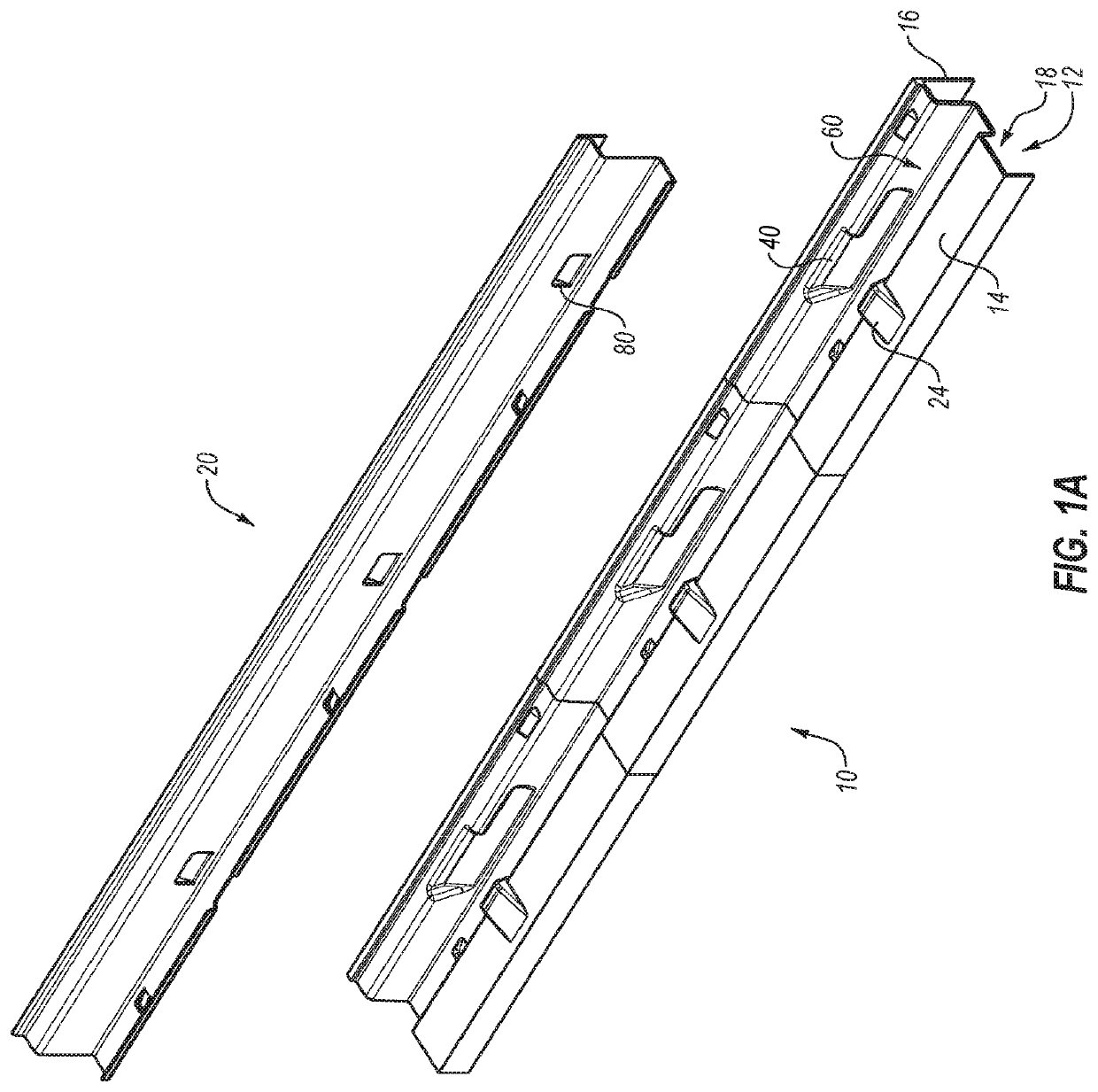
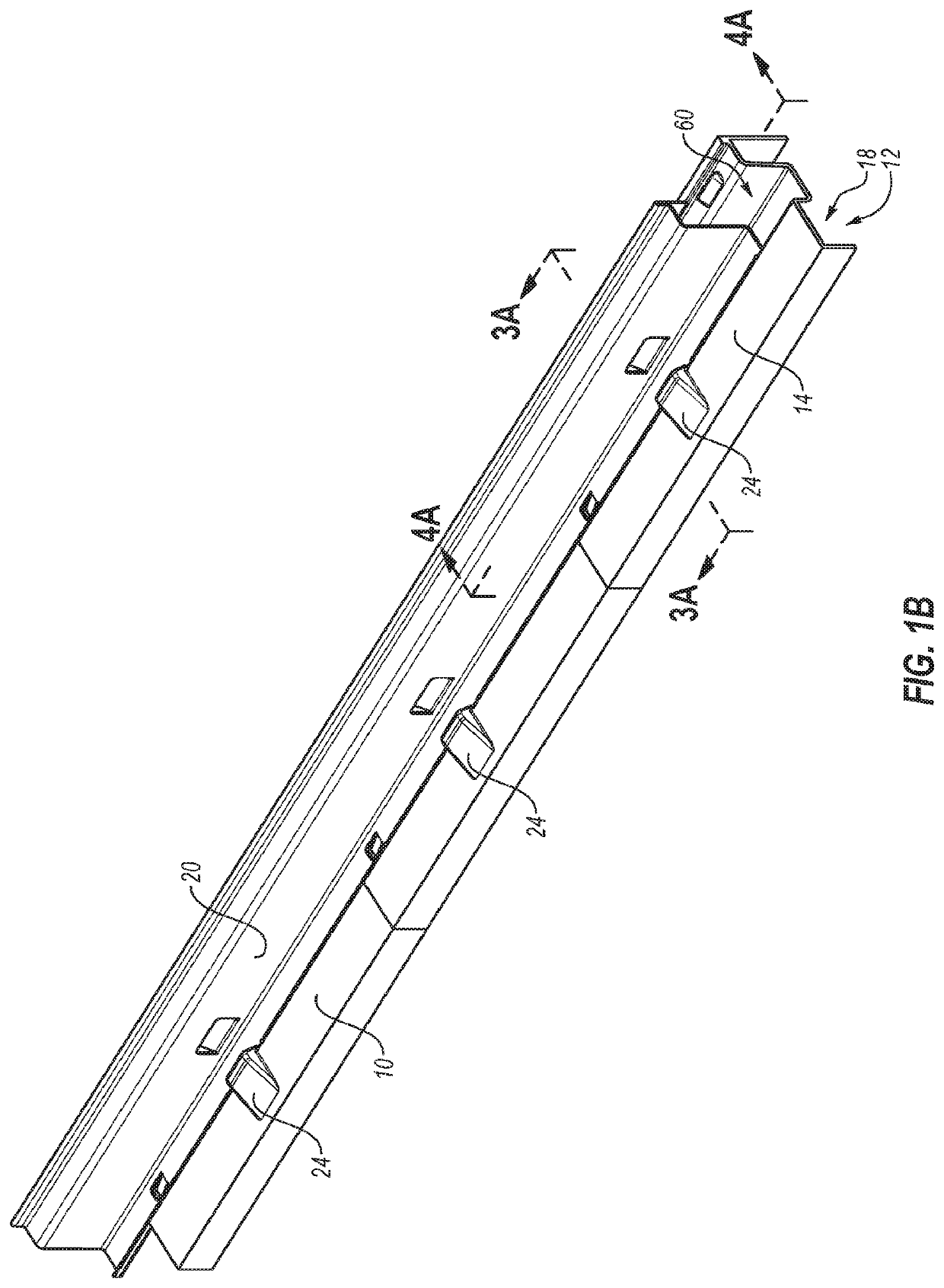
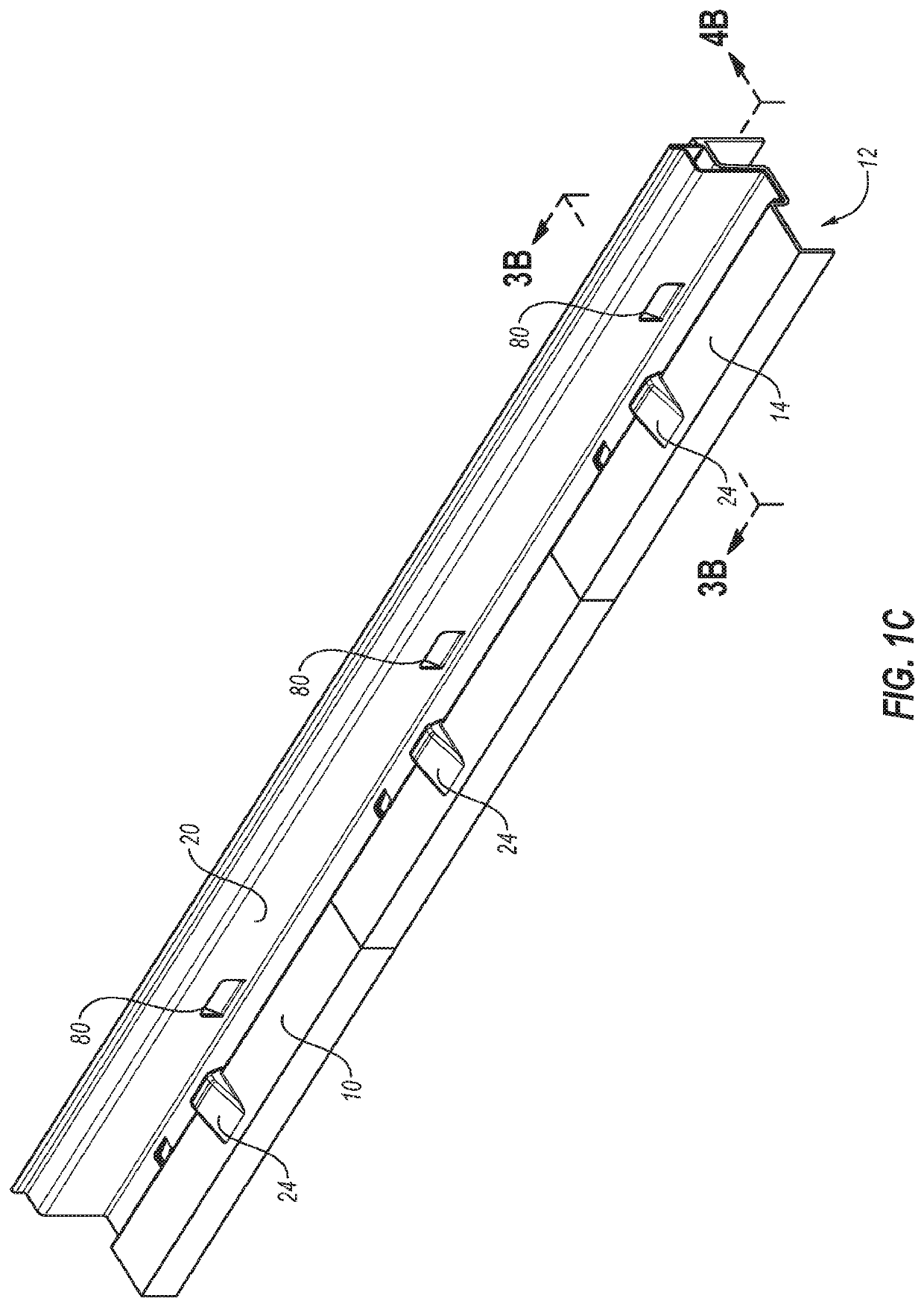
[0056]The following exemplary embodiments are generally described in connection with blow-molded plastic structures such as a tabletop. The principles of the present invention, however, are not limited to a tabletop. In particular, the principles of the present invention may be implemented in other articles of furniture and in other structures that include blow-molded plastic components. In addition, it will be understood that, with the benefit of the present disclosure, the structures can have a variety of shapes, sizes, configurations, and arrangements. Moreover, the invention disclosed herein and components thereof may be successfully used in connection with other types of structures such as furniture (e.g., tables, picnic tables, chairs, etc.), objects (e.g., sheds, deck boxes, coolers, garden boxes, playground equipment, sporting goods, water sports equipment, etc.), and the like.

[0057]To assist in the description of exemplary embodiments shown in the accompanying figures, word...


PUM

PropertyMeasurementUnit
angleaaaaaaaaaa
angleaaaaaaaaaa
angleaaaaaaaaaa

Abstract

A blow-molded plastic structure, such as a tabletop, may include an undercut. For example, the tabletop may include a frame receiving portion and a frame connecting structure with an undercut may be disposed in the frame receiving portion. A portion of the frame may contact or engage the frame connecting structure, such as the undercut, when the frame is connected to the tabletop. In an exemplary embodiment, a first side of the frame receiving portion may include a first frame connecting portion with an undercut and a second side of the frame receiving portion may include a second frame connecting portion with an undercut. The first frame connecting portion with an undercut may be disposed on an opposing surface from the second frame connecting portion with an undercut.

Description

CROSS-REFERENCE TO RELATED APPLICATIONS[0001]This application is a continuation of U.S. patent application Ser. No. 16 / 776,385, filed Jan. 29, 2020, which claims priority to and the benefit of U.S. Provisional Patent Application Ser. No. 62 / 800,318, filed Feb. 1, 2019.[0002]This application is a continuation of U.S. patent application Ser. No. 16 / 778,717, filed Jan. 31, 2020, which claims priority to and the benefit of U.S. Provisional Patent Application Ser. No. 62 / 800,318, filed Feb. 1, 2019.[0003]Each of these applications and patents are hereby incorporated by reference in its entirety.BACKGROUNDField of the Invention[0004]The present invention generally relates to structures that are at least partially constructed from blow-molded plastic and, more particularly, to blow-molded plastic structures including an undercut.Description of Related Art[0005]Blow-molding is a manufacturing process by which hollow plastic parts are formed. The blow-molding process typically begins with a ...

Claims


Application Information

Patent Timeline
Patent Type & Authority Applications(United States)
IPC IPC(8): A47B7/00A47B13/00A47B13/02
CPCA47B7/00A47B13/003A47B13/02A47B2200/0011A47B2220/008A47B2200/001A47B2230/16B29C49/54A47B13/00B29C49/00A47B3/06A47B3/08A47B3/12B29L2031/44B29L2031/00A47B13/08B29C49/0031B29C49/541B29L2031/448B29L2031/7282
Inventor JONES, SCOTTMONSEN, CHARLESBOYDSTON, KEVINCLEGG, FRANK M.
Owner LIFETIME PRODUCTS
Why Eureka
Try Eureka