Eureka AIR delivers breakthrough ideas for toughest innovation challenges, trusted by R&D personnel around the world.

Cryopump

Active Publication Date: 2021-07-22
BOE TECH GRP CO LTD +1
View PDF0 Cites 0 Cited by
  • Summary
  • Abstract
  • Description
  • Claims
  • Application Information

AI Technical Summary

Benefits of technology

The present disclosure provides a cryopump with a baffle that has a gas passage with an inlet and an outlet. The baffle completely covers the suction port and the gas passage includes a first portion and a second portion that intersect with each other. The invention has technical effects that improve the performance of the cryopump by reducing the amount of gas that enters the pump and increasing the efficiency of the cryopump.

Problems solved by technology

Since a heat radiation of the vacuum chamber will affect the temperature of the cold head, the greater the heat radiation (especially the evaporation of organic materials with higher temperature), the more difficult the temperature of the cold head to maintain, if the temperature of the cold head rises to 15K, the cold head will fail to make it impossible to maintain the vacuum state of the vacuum chamber.

Method used


Image

  • Cryopump
  • Cryopump
  • Cryopump

Examples


Embodiment Construction

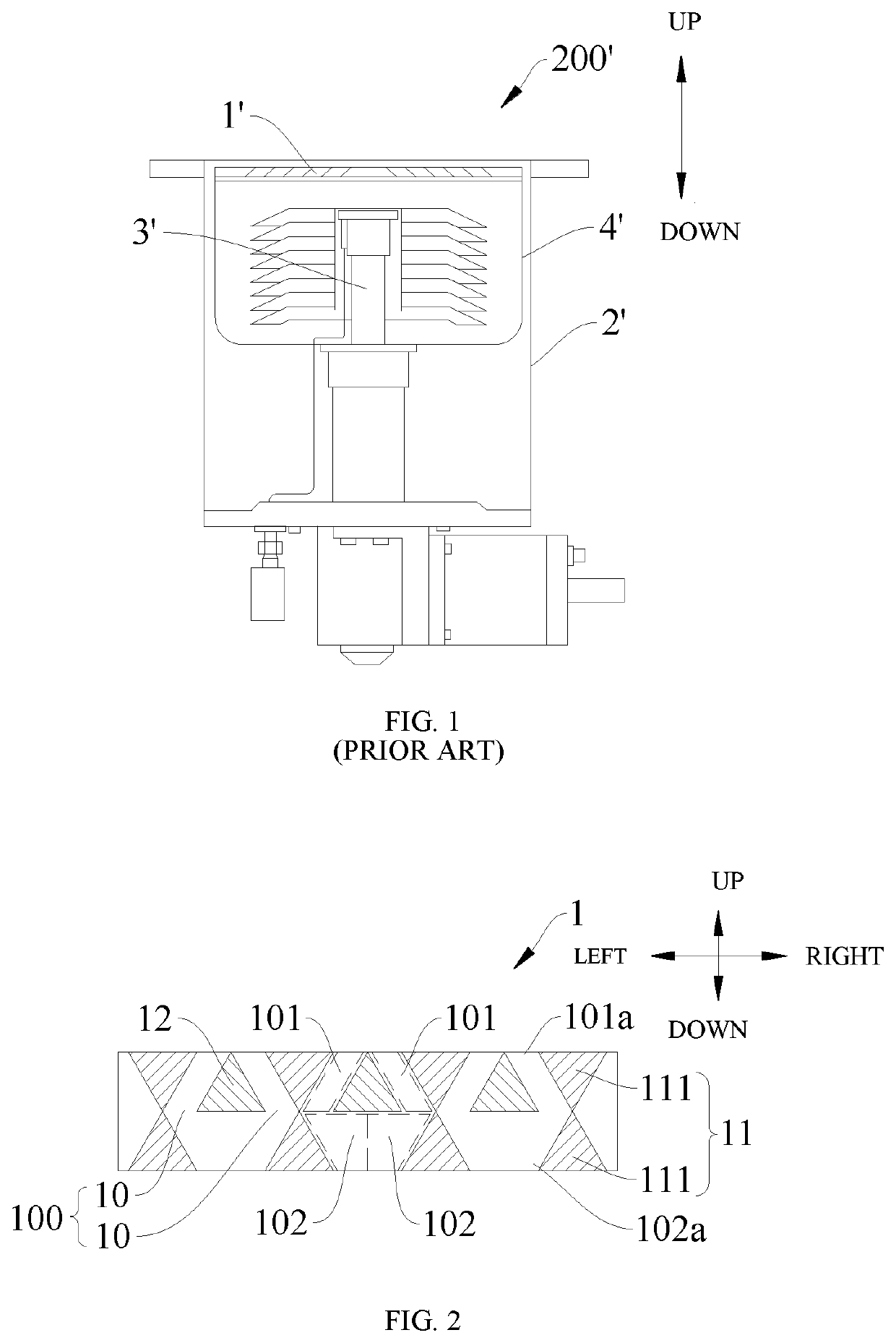
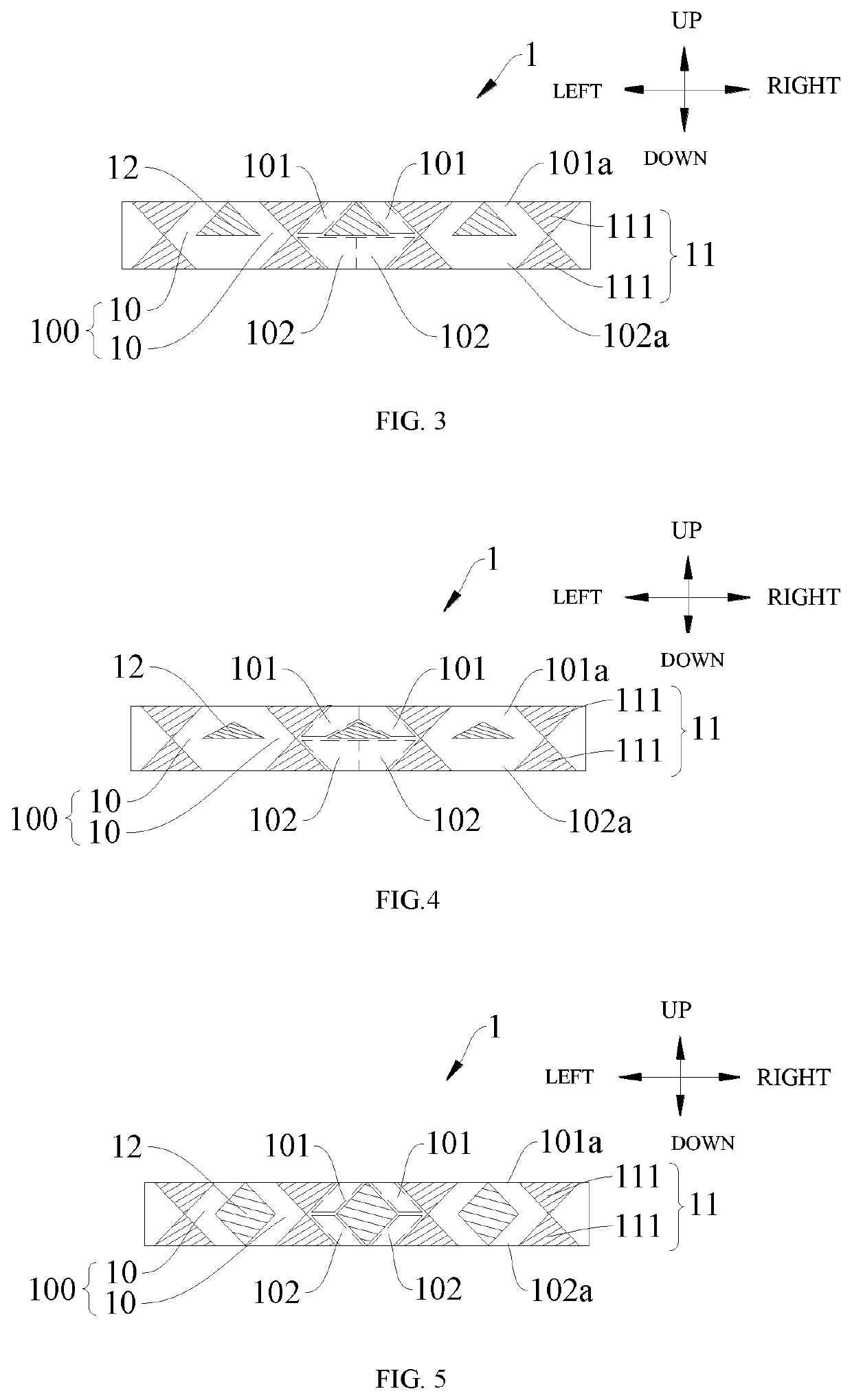
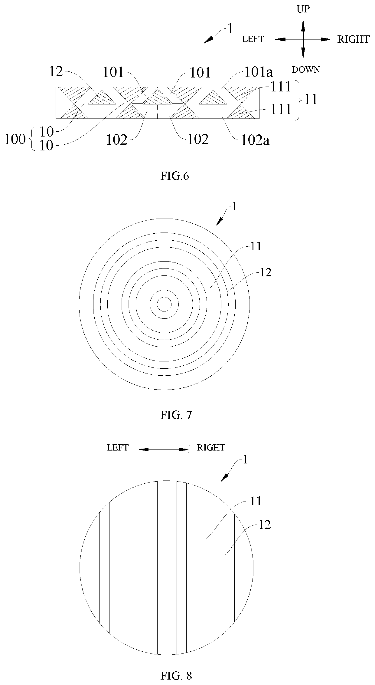
[0024]The embodiments of the present disclosure will be illustrated in detail below, examples of which are shown in the drawings, wherein the same or like reference numerals will be used to refer to the same or like elements or elements with the same or similar functions. The embodiments described below with reference to the accompanying drawings are exemplary only, and shall be only for the purpose of interpreting but not for limiting the present disclosure.

[0025]In the description of the present disclosure, it should be understood that the terms “center”, “longitudinal”, “transverse”, “height”, “upper”, “lower”, “left”, “right”, “horizontal”, “inner”, “outer” and etc. refer to orientation or positional relationship shown in the drawings, and are merely for the convenience of illustration and simplification, but do not intend to indicate or imply that a device or component referred to must have a particular orientation, or must be produced and operated in a particular orientation, ...


PUM


Abstract

The embodiments of the present disclosure relates a cryopump including a pump housing including a suction port, a cold head located within the pump housing, a shielding element located within the pump housing and covering the cold head, a baffle at the suction port, the baffle including a gas passage with an inlet and an outlet, an orthographic projection of the baffle to the cross section of the pump housing completely covers an orthographic projection of the suction port thereto, the gas passage includes a first portion and a second portion intersecting with each other, the inlet is defined by one end of the first portion, the outlet is defined by one end of the second portion.

Description

CROSS REFERENCE TO RELATED APPLICATIONS[0001]This patent application is a National Stage Entry of PCT / CN2018 / 078256 filed on Mar. 7, 2018, which claims the benefit and priority of Chinese Patent application No. 201720798098.9 filed on Jul. 3, 2017, the disclosures of which are incorporated herein by reference in their entirety as part of the present application.BACKGROUND[0002]The embodiments of the present disclosure relate to a cryopump.[0003]In actual production, some products, such as a display screen, need to be fabricated and used in a vacuum environment, and the vacuum environment required to fabricate these products is achieved by means of a cryopump.[0004]By withdrawing the gas in a vacuum chamber and cooling and adsorbing the gas within in the cryopump, the vacuum chamber of the cryopump may reach a desired vacuum state. Therefore, a primary part of the cryopump is an internal cold head therein. Only when the temperature of the cold head is lower than 15K, H2, He and other...

Claims


Application Information

Patent Timeline
IPC IPC(8): F04B37/08
CPCF04B37/08
Inventor LIU, JINDONGKONG, QINGWUGUO, XIONGFEI
Owner BOE TECH GRP CO LTD
Why Eureka
Eureka Blog
Learn More