Uniformly lit planar field of illumination

a planar field, uniform illumination technology, applied in the direction of instruments, lighting support devices, with built-in power, etc., can solve the problem of no standard for luminaires and light sources

Active Publication Date: 2021-08-19
LIGHTING DEFENSE GRP
View PDF0 Cites 2 Cited by
  • Summary
  • Abstract
  • Description
  • Claims
  • Application Information

AI Technical Summary

Problems solved by technology

As a result, there are no standards for luminaires and light sources' form other than what is required by code / s.
When it comes to lamp source, drivers and batteries, the manufacturers prefer using off the shelf products typically fabricated by others, often having no knowledge of their components' ultimate purpose.

Method used


Image

  • Uniformly lit planar field of illumination
  • Uniformly lit planar field of illumination
  • Uniformly lit planar field of illumination

Examples


Embodiment Construction

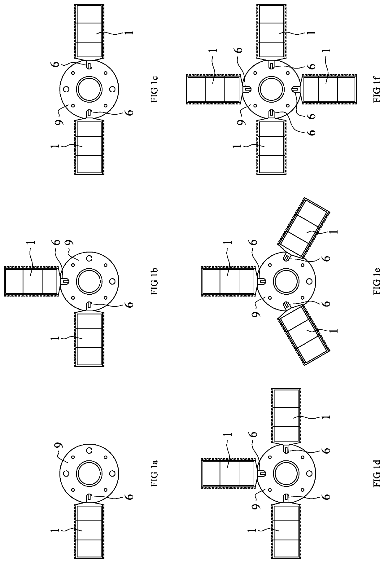
[0085]The present innovation relates to an illumination solution that forms a continuous and uniform illuminated path. The path width, illumination light levels and uniformity ratios can be maintained regardless of the building's ceiling height.

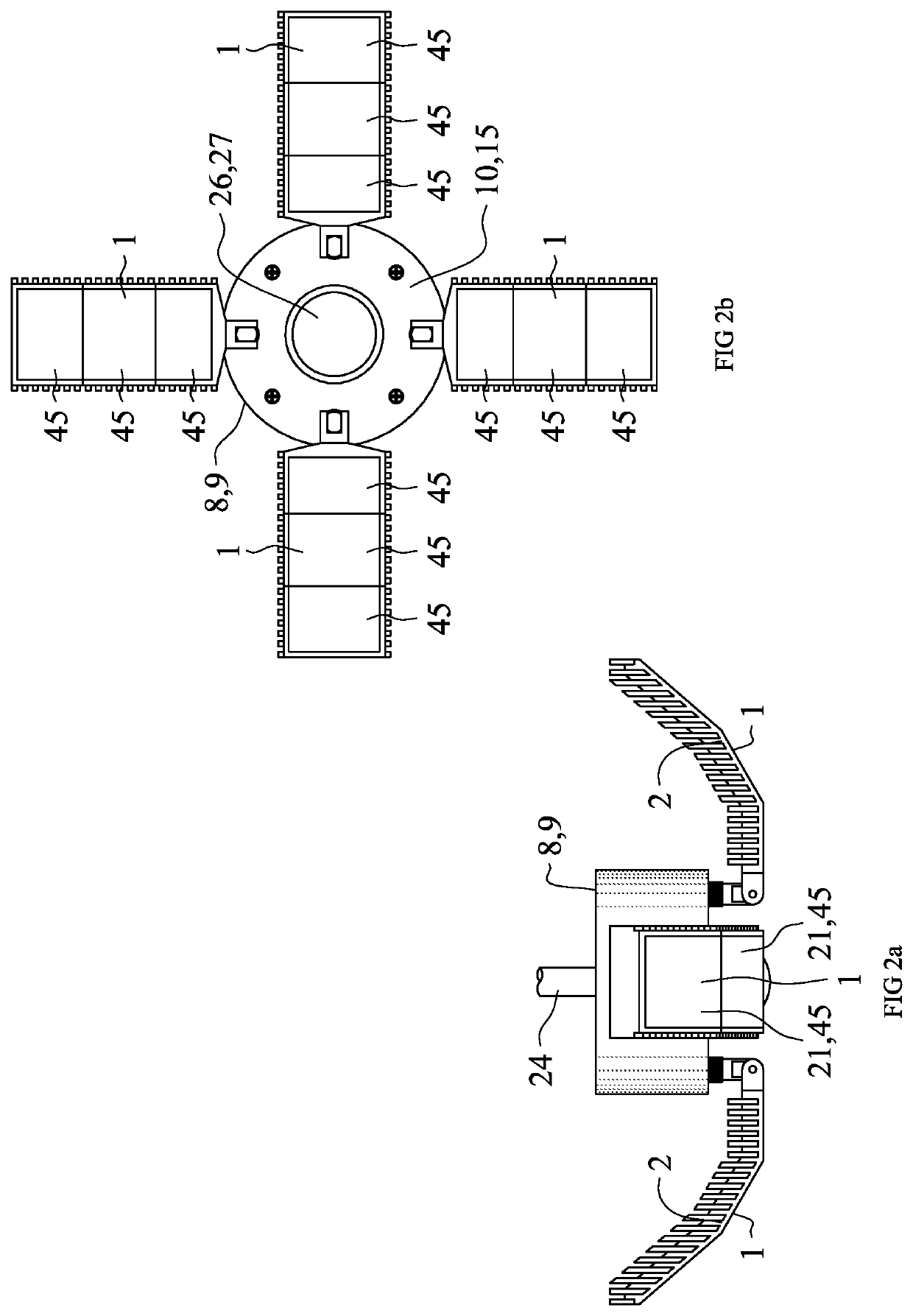
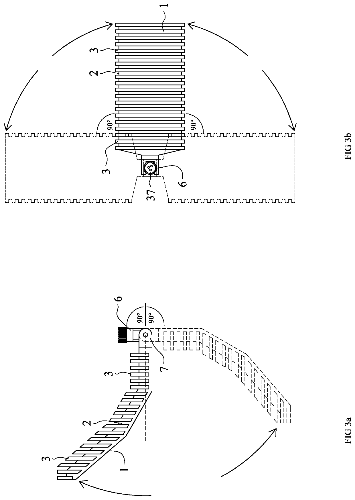
[0086]Referring to the drawings, the present innovation addresses the code requirements for illuminated path of egress by developing a novel heatsink light source (HLS) 1 embodiment. The novel embodiment is configured to illuminate a long path uniformly, consuming low energy and eliminating the need for aiming the HLS 1 embodiment regardless of the embodiment's mounting height. This novel design employs mechanical, optical and electronic concepts that differ from today's art.

[0087]The mandated code path of egress 50 requires that in the event of a power outage, building occupants should be able to follow an illuminated path to the building exit doors. In addition to the illuminated path, illuminated exit sign 35 chevrons 36 shall point in the...


PUM


Abstract

A light emitting embodiment uniformly illuminating a planar field configured to operate in conjunction with other like embodiments in proximity to form a continuous uniformly lit planar pathway and/or field of illumination.

Description

CROSS REFERENCE TO RELATED APPLICATION[S][0001]This application claims priority to U.S. Provisional patent application entitled “EGRESS LIGHT,” Ser. No. 62 / 977,994, filed Feb. 18, 2020, the disclosure of which are hereby incorporated entirely herein by reference.BACKGROUND OF THE INVENTION[0002]National and local building codes mandate the use of egress lighting luminaires in buildings occupied by humans. The egress lighting luminaires conforming to code requirements generate an illuminated “legal path of egress”. This path of egress enables building occupants to find their way out of the building in the event of main building power outage. In such an event, the building egress lighting is turned on, forming a continuous path of egress to the building's “legal exit doors”. Some jurisdictions also require illumination of a path of egress at the exterior side of the legal exit doors.[0003]The egress lighting luminaires are commonly powered by one of the following means: A. Integral ba...

Claims


Application Information

Patent Timeline
Patent Type & Authority Applications(United States)
IPC IPC(8): F21V29/74F21S9/02F21V33/00G09F13/04
CPCF21V29/745F21S9/024G09F2013/0436G09F13/0413G09F2013/0459F21V33/0076F21S8/043F21V14/02F21V21/28F21W2111/00F21Y2115/10F21V21/30G09F13/0436G09F2013/05
Inventor SPIRO, DANIEL S.
Owner LIGHTING DEFENSE GRP
Why Eureka
Try Eureka