Fuel cell and manufacturing method thereof

Active Publication Date: 2021-09-09
TOYOTA JIDOSHA KK
View PDF0 Cites 0 Cited by
  • Summary
  • Abstract
  • Description
  • Claims
  • Application Information

AI Technical Summary

Benefits of technology

The patent text describes a fuel cell with a gasket on its surface. When a sealing portion needs to be formed, heat input is often hindered by the gasket, which can result in an insufficient sealing. This problem is addressed in the fuel cell by restraining heat input to the sealing portion and improving the sealing strength. This results in a better sealing characteristic in the fuel cell.

Problems solved by technology

In a fuel cell configured such that a gasket is provided on an outer surface of a gas separator as such, when a sealing portion in a cell is to be formed at a position overlapping with the gasket in a laminating direction by heating from the outer surface side of the gas separator, heat input to form the sealing portion is restrained by the gasket, so that a sealing characteristic in the sealing portion might become insufficient.
Particularly, insufficiency in heat input to form the sealing portion easily occurs in a part where two gaskets are formed side by side as described above.

Method used


Image

  • Fuel cell and manufacturing method thereof
  • Fuel cell and manufacturing method thereof
  • Fuel cell and manufacturing method thereof

Examples


Embodiment Construction

[0018]A. Overall Configuration of Fuel Cell

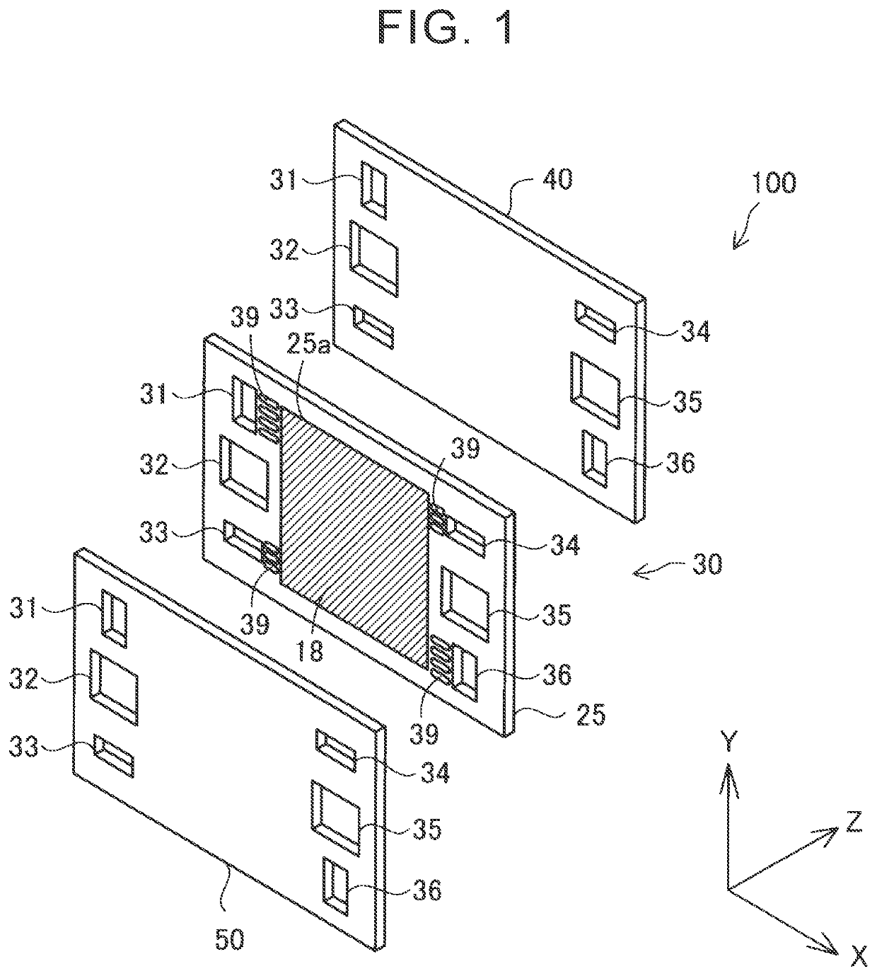
[0019]FIG. 1 is an exploded perspective view illustrating the outline of a configuration of a single cell 100 provided in a fuel cell as a first embodiment of this disclosure. Note that FIG. 1 and drawings (described later) each schematically illustrate a state of each part in the fuel cell of the present embodiment. Accordingly, the size of each part illustrated herein does not indicate a specific size. The fuel cell of the present embodiment has a stack structure in which a plurality of single cells 100 is laminated. The fuel cell of the present embodiment is a solid polymer fuel cell but can be other types of fuel cells such as a solid oxide fuel cell. The single cell 100 includes a membrane electrode gas diffusion layer assembly 18 (hereinafter also referred to as an MEGA 18), a first gas separator 40, a second gas separator 50, and a resin sheet 25.

[0020]The MEGA 18 includes a membrane electrode assembly (hereinafter also referred to a...


PUM


Abstract

A single cell includes a linear sealing portion bonded to a pair of gas separators, the sealing portion being provided between the gas separators. A fuel cell in which a plurality of single cells is laminated includes: a gasket provided between the single cells adjacent to each other; a first manifold communicating with an inside-cell gas passage; and a second manifold communicating with an inter-cell refrigerant passage. The gasket includes a first gasket placed to surround the outer periphery of the first manifold and configured to seal the first manifold, and a second gasket configured to seal the second manifold and an inter-cell refrigerant passage. When the fuel cell is viewed from the laminating direction, the first gasket, the sealing portion, and the second gasket are placed in this order from the first manifold toward the second manifold between the first manifold and the second manifold.

Description

INCORPORATION BY REFERENCE[0001]The disclosure of Japanese Patent Application No. 2020-039465 filed on Mar. 9, 2020 including the specification, drawings and abstract is incorporated herein by reference in its entirety.BACKGROUND1. Technical Field[0002]This disclosure relates to a fuel cell and a manufacturing method thereof2. Description of Related Art[0003]Generally, a fuel cell has a stack structure in which a plurality of single cells is laminated, and a refrigerant passage is provided between the single cells thus laminated.[0004]On this account, respective sealing structures for sealing reactant gas or refrigerant are provided in each single cell and between single cells adjacent to each other. As the sealing structure provided between the single cells adjacent to each other, a sealing structure including a gasket surrounding a gas manifold hole and a gasket surrounding a region including a refrigerant manifold hole has been known (e.g., see Japanese Unexamined Patent[0005]App...

Claims


Application Information

Patent Timeline
IPC IPC(8): H01M8/0276H01M8/2483H01M8/242H01M8/0286
CPCH01M8/0276H01M8/0286H01M8/242H01M8/2483H01M8/2465H01M8/2404H01M8/1004Y02E60/50Y02P70/50
Inventor KURIHARA, TAKUYASATO, KENJI
Owner TOYOTA JIDOSHA KK
Why Eureka
Try Eureka