
Two-part seal plate for vessel sealer and method of manufacturing same

a sealer and seal plate technology, applied in the field of electrosurgical instruments, can solve problems such as trapped lower plates

Inactive Publication Date: 2021-10-21
TYCO HEALTHCARE GRP LP
View PDF1 Cites 0 Cited by
  • Summary
  • Abstract
  • Description
  • Claims
  • Application Information

AI Technical Summary

Benefits of technology

The present disclosure relates to a jaw member for an end effector assembly of a surgical instrument. The jaw member includes a support base and an electrical jaw lead. The lower plate of the jaw member is made of a non-conductive material, and the upper plate has a sealing plate with a cavity for receiving the lower plate. The sealing plate has a series of grooves and a knife slot for reciprocation of a knife. The lower plate is secured to the non-tissue engaging side of the upper plate, and the extension portion of the lower plate acts as a stop member to control the distance between the jaw member and an opposing jaw member of the end effector assembly. The method of manufacturing the sealing plate involves fabricating a series of grooves through the upper plate and securing the lower plate to the non-tissue engaging side of the upper plate.

Problems solved by technology

The lower plate may also be trapped during an overmolding process.

Method used


Image

  • Two-part seal plate for vessel sealer and method of manufacturing same
  • Two-part seal plate for vessel sealer and method of manufacturing same
  • Two-part seal plate for vessel sealer and method of manufacturing same

Examples


Embodiment Construction

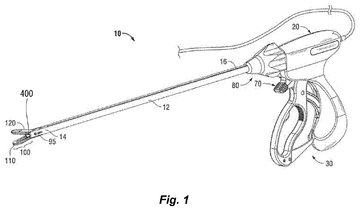
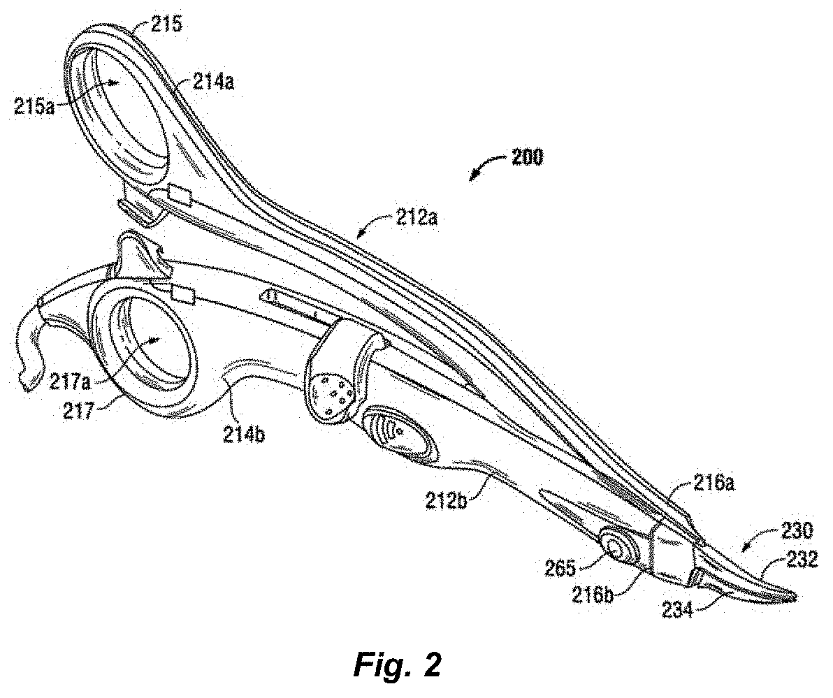
[0032]Particular embodiments of the present disclosure are described hereinbelow with reference to the accompanying drawings; however, it is to be understood that the disclosed embodiments are merely exemplary of the disclosure and may be embodied in various forms. Well-known functions or constructions are not described in detail to avoid obscuring the present disclosure in unnecessary detail. Therefore, specific structural and functional details disclosed herein are not to be interpreted as limiting, but merely as a basis for the claims and as a representative basis for teaching one skilled in the art to variously employ the present disclosure in virtually any appropriately detailed structure.

[0033]Like reference numerals may refer to similar or identical elements throughout the description of the figures. As shown in the drawings and described throughout the following description, as is traditional when referring to relative positioning on a surgical instrument, the term “proximal...


PUM


Abstract

An end effector assembly includes a pair of opposing jaw members, one or both of the jaw members having a support base and an electrical jaw lead adapted to operably connect to an electrosurgical generator. A sealing plate is operably coupled to the support base and includes: an upper plate having an outer peripheral edge that extends therefrom and that defines a cavity configured to receive a lower plate; and a series of grooves defined within the upper plate and projecting therethrough to expose the lower plate. One or both of the upper plate or the lower plate is operably coupled to the electrical lead.

Description

BACKGROUNDTechnical Field[0001]The present disclosure relates to an apparatus for performing an electrosurgical procedure. More particularly, the present disclosure relates to an apparatus for performing an electrosurgical procedure and a method of manufacturing the same that employs an end effector assembly including a two-part sealing plate to enhance gripping and sealing tissue.Background of the Related Art[0002]Electrosurgical apparatuses (e.g., electrosurgical forceps) are well known in the medical arts and typically include a handle, a shaft and an end effector assembly operatively coupled to a distal end of the shaft that is configured to manipulate tissue (e.g., grasp and seal tissue). Electrosurgical forceps utilize both mechanical clamping action and electrical energy to effect homeostasis by heating the tissue and blood vessels to coagulate, cauterize, fuse, seal, cut, desiccate, and / or fulgurate tissue.[0003]Electrosurgical forceps may be so-called open forceps for use w...

Claims


Application Information

Patent Timeline
Patent Type & Authority Applications(United States)
IPC IPC(8): A61B18/14
CPCA61B18/1445A61B2017/00526A61B2017/2936A61B2018/0063A61B2018/126A61B2018/1455A61B2017/2911
Inventor FRY, MONTE S.SIMS, GRANT T.MCCULLOUGH, JR., ROBERT F.
Owner TYCO HEALTHCARE GRP LP
Features
  • Generate Ideas
  • Intellectual Property
  • Life Sciences
  • Materials
  • Tech Scout
  • Unparalleled Data Quality
  • Higher Quality Content
  • 60% Fewer Hallucinations
Learn More