Circuit for switching an ac voltage

a technology of ac voltage and ac voltage, which is applied in the direction of electric ignition installation, mechanical equipment, machines/engines, etc., can solve the problems of higher cost of additional dc voltage sources and additional coils, pin diodes are not able to block themselves at its own volition, and the intrinsic region of charge carriers is no longer able to follow the rapid change of direction of higher-frequency ac voltage, etc., to prevent the capacitor from shorting, the voltage induced

Active Publication Date: 2021-11-18
ROSENBERGER HOCHFREQUENZTECHNIK GMBH & CO KG
View PDF0 Cites 1 Cited by
  • Summary
  • Abstract
  • Description
  • Claims
  • Application Information

AI Technical Summary

Benefits of technology

[0031]According to the invention, a first end connection of the first series circuit is connected to the input terminal, and a second end connection of the first series circuit is connected to the output terminal. The first series circuit is thus integrated into the high-frequency transmission path. In a distribution circuit containing a plurality of parallel-connected high-frequency transmission paths, only a single high-frequency transmission path, and thus a single PIN diode, is ever conductive, while all of the other high-frequency transmission paths or PIN diodes are blocked. In a distribution circuit containing a first series circuit integrated into the high-frequency transmission path, a current thus flows only in one PIN diode at any operating time, while, in a distribution circuit with a circuit implementation according to WO 01 / 35530 A2, one current flows in a plurality of diodes in each case. The circuit implementation according to the invention is thus advantageously minimized in terms of energy consumption in comparison with the prior art.
[0081]The motor-driving circuit according to the invention creates a circuit that is able to switch on an AC voltage generated by a single AC voltage source in the cyclical alternation of a number of electrical spark plugs. The motor-driving circuit according to the invention thus advantageously makes it possible to achieve a significant saving in terms of AC voltage sources.

Problems solved by technology

The charge carriers in the intrinsic region are no longer able to follow the rapid change of direction of the higher-frequency AC voltage.
However, this self-conducting characteristic of the PIN diode when a higher-frequency AC voltage is present has the disadvantage that the PIN diode is not able to block itself at its own volition.
As may be seen in FIG. 1, the operation of a PIN diode requires not only a DC voltage network for forward-biasing the PIN diode, but also, disadvantageously, a DC voltage network for reverse-biasing the PIN diode.
The associated higher cost of an additional DC voltage source and of additional coils, which prevent the high-frequency signal from being fed into the DC voltage network, represents a significant application obstacle in cost-sensitive fields of application, such as for example in the automotive sector.
Wiring the PIN diode in this way significantly worsens the high-frequency transmission behavior of the high-frequency transmission path.
In order to achieve this high current-carrying capacity, considerable effort has to be made when designing the high-frequency amplifier, the capacitor and the PIN diode.
In addition, such wiring of a PIN diode also requires the capacitor of the series circuit in addition to the coupling-out capacitor, such that this does not result in a solution with a minimum number of components.
Such wiring of a PIN diode is therefore unsuitable for a distribution circuit in which a single high-frequency transmission path is always conductive and all of the other high-frequency transmission paths are blocked.

Method used


Image

  • Circuit for switching an ac voltage
  • Circuit for switching an ac voltage
  • Circuit for switching an ac voltage

Examples


Embodiment Construction

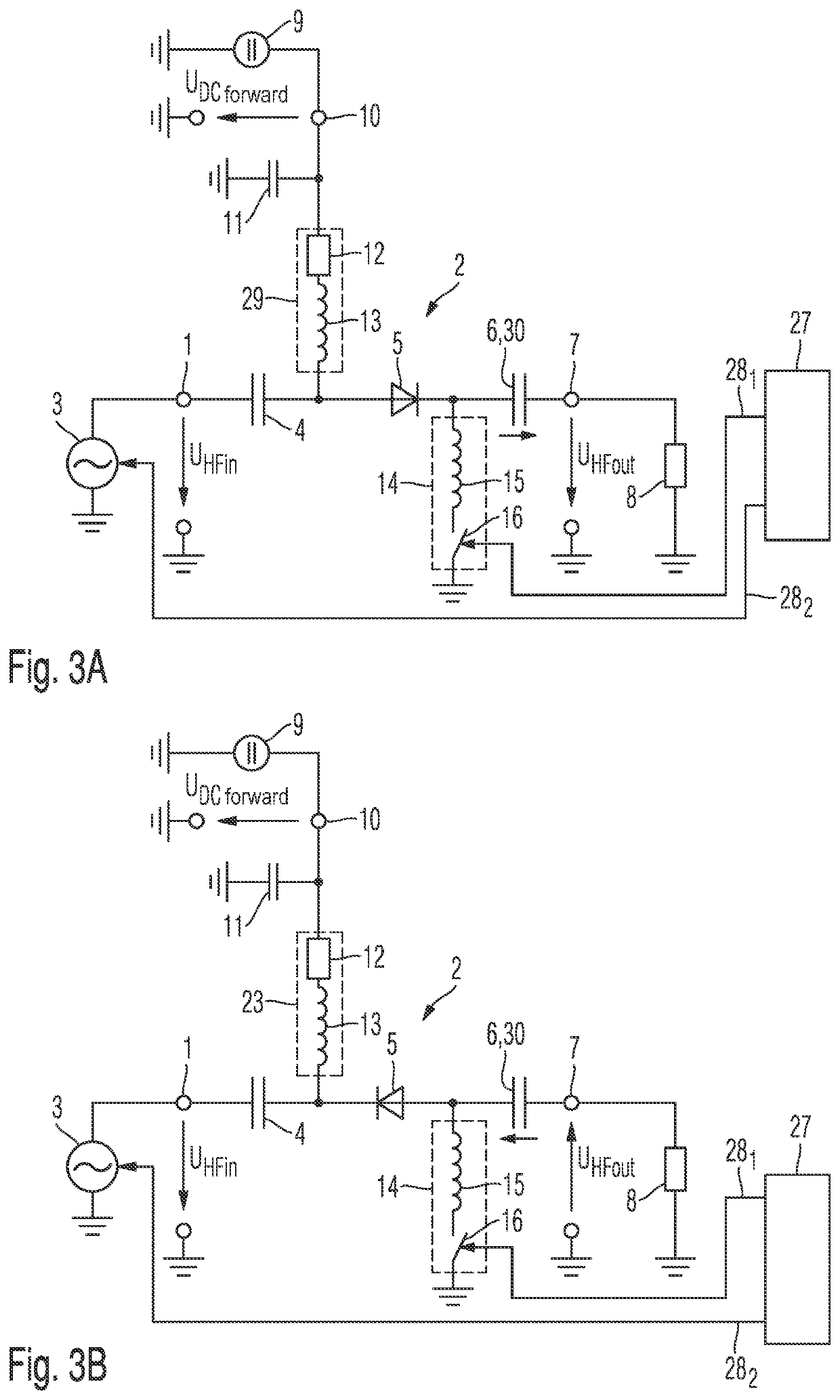
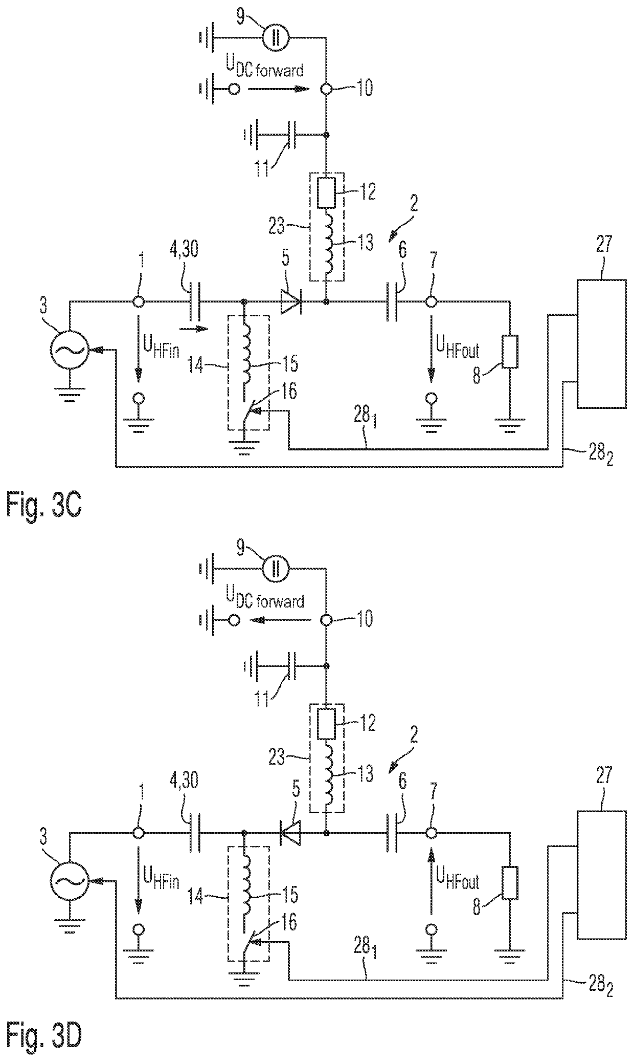
[0104]The four variants of a circuit according to the invention for switching an AC voltage are explained in detail below with reference to FIGS. 3A to 3D:

[0105]An AC voltage source 3 is connected to the input terminal 1 of the circuit 2 according to the invention for switching an AC voltage. The AC voltage source 3 is preferably a voltage source for generating a high-frequency voltage. This may be for example a frequency oscillator or any other high-frequency circuit that generates a high-frequency voltage with a specific settable or fixed frequency and a specific settable or fixed amplitude.

[0106]This AC voltage source 3 or voltage source for generating a high-frequency voltage impresses a specific AC voltage or high-frequency voltage into the circuit 2 according to the invention for switching an AC voltage. As an alternative, an AC current source or a current source for generating a high-frequency current with a parallel-connected resistor are also conceivable, by way of which an...


PUM

PropertyMeasurementUnit
frequenciesaaaaaaaaaa
frequencyaaaaaaaaaa
frequencyaaaaaaaaaa

Abstract

The present invention relates to a circuit for switching an AC voltage. It contains an input terminal able to be connected to an AC voltage source, an output terminal able to be connected to a load impedance, and a first series circuit. This series circuit comprises a diode and a circuit for storing electrical charges. The series circuit has a first end connection that is connected to the input terminal and a second end connection that is connected to the output terminal. The circuit for switching an AC voltage furthermore contains a DC voltage source, which is connected to an electrical connection between the diode and the input terminal or to an electrical connection between the diode and the output terminal and is designed to impress a DC current in the diode. The circuit for switching an AC voltage finally contains a first switch that is connected to an electrical connection between the diode and the circuit for storing electrical charges at one terminal. The first switch is designed to switch between a switching state in which a potential dependent on a reference potential is present at the electrical connection between the diode and the circuit for storing electrical charges, and a switching state in which an electrical floating potential is present in the electrical connection between the diode and the circuit for storing electrical charges.

Description

FIELD OF THE INVENTION[0001]The present invention relates to a circuit for switching an AC voltage.TECHNICAL BACKGROUND[0002]In order to switch a high-frequency voltage, use is preferably made of a PIN diode, as illustrated for example in KR 101594517 B1. Such a PIN diode has what is called an intrinsic region between a P-doped region and an N-doped region. In the case of a forward-biased PIN diode, a multiple concentration of charge carriers from the P-doped and N-doped regions, in comparison with the charge carrier concentration already intrinsically present in the intrinsic region, is injected into this intrinsic region. This high charge carrier injection from the P-doped and N-doped regions shifts the electric field from the P-doped and N-doped region deep into the intrinsic region. This accelerates the charge carrier transport within the PIN diode and thus makes it suitable for high-frequency applications. In particular at higher frequencies starting from 10 MHz, the PIN diode ...

Claims


Application Information

Patent Timeline
Patent Type & Authority Applications(United States)
IPC IPC(8): H02M5/458
CPCH02M5/458H02M7/10H02M7/25H03K17/74H02M5/20F02P3/01F02P3/04F02P9/007
Inventor FUCHS, MARTINHUBER, CHRISTOPHWINKLER, JOHANNESGRÖGER, SVENVAN DELDEN, MARCELNOTZON, GORDONMUSCH, THOMAS
Owner ROSENBERGER HOCHFREQUENZTECHNIK GMBH & CO KG
Why Eureka
Try Eureka