

Charged particle irradiation apparatus
a technology of irradiation apparatus and charged particles, which is applied in the field of charged particle irradiation apparatus, can solve the problems of deteriorating measurement accuracy
- Summary
- Abstract
- Description
- Claims
- Application Information
AI Technical Summary
Benefits of technology
Problems solved by technology
Method used
Image

Examples
first embodiment
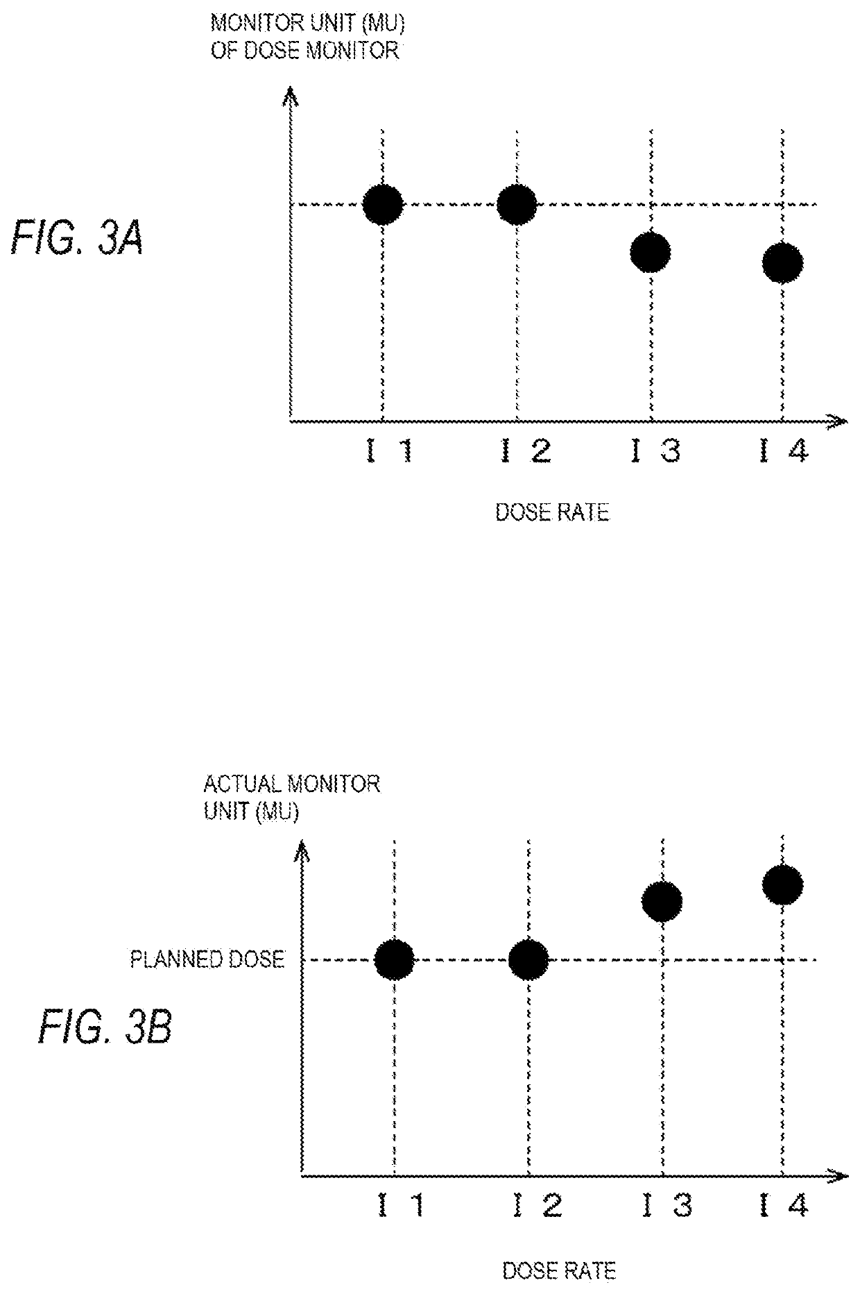
[0044]The first embodiment of the present invention relates to a charged particle irradiation apparatus that performs scanning with a charged particle beam and irradiates an irradiation target spot by spot. In particular, the charged particle irradiation apparatus of the present embodiment mainly corrects a difference between an actual dose delivered in an irradiation target and a dose measured by a dose monitor, and the difference is caused by influence of ion recombination in the dose monitor provided to an irradiation nozzle.
[0045]Charged Particle Irradiation Apparatus 10
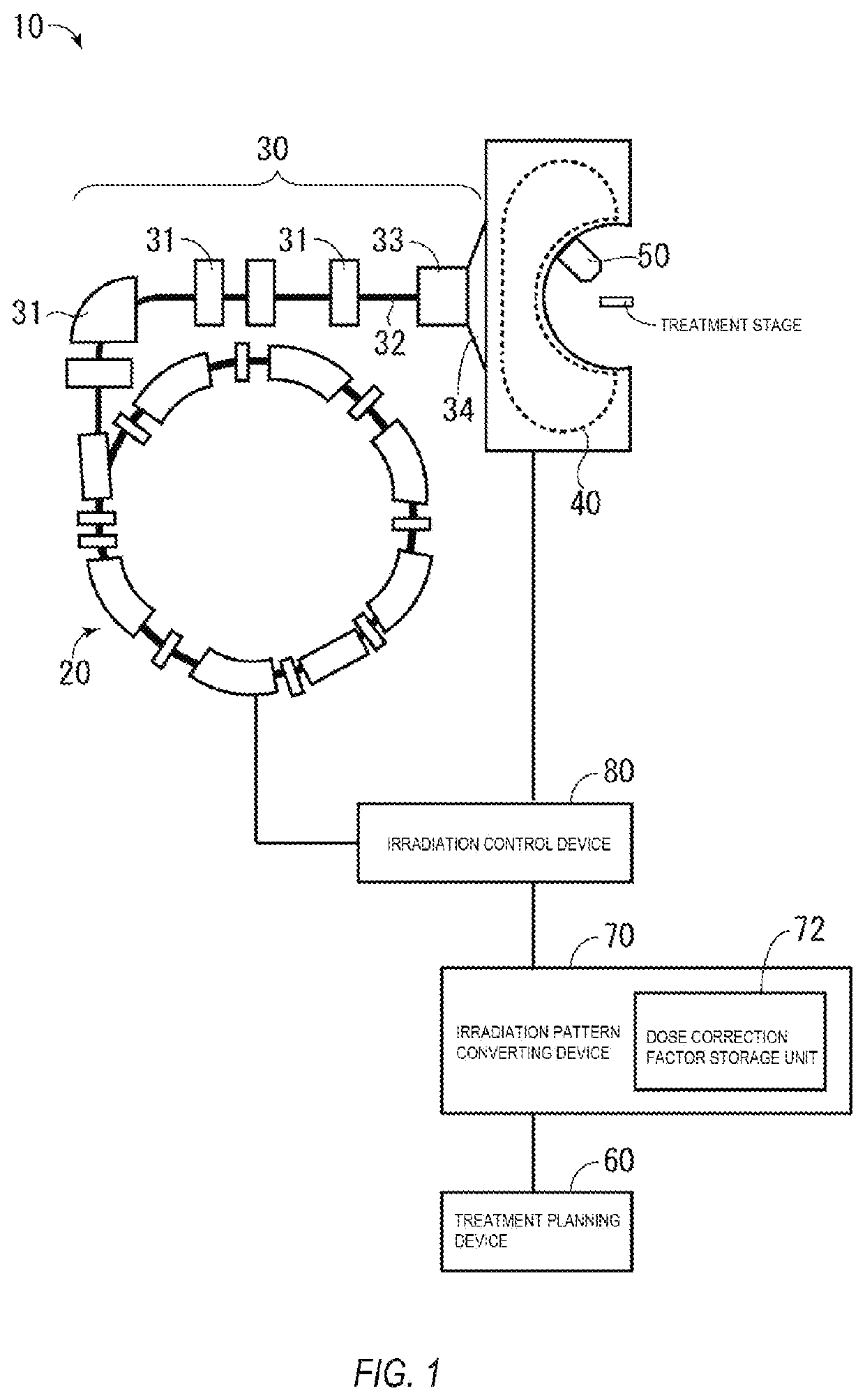
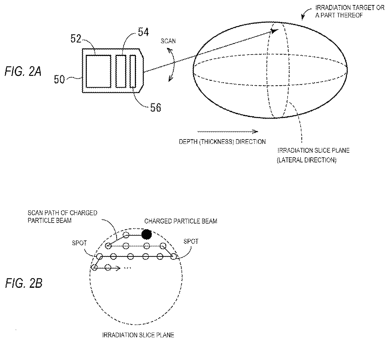
[0046]FIG. 1 is a schematic diagram of a configuration of a charged particle irradiation apparatus 10, and FIG. 2A and FIG. 2B are schematic diagrams of an irradiation nozzle 50 and scanning irradiation.
[0047]The charged particle irradiation apparatus 10 has an accelerator 20, a charged particle beam transport system 30, a focusing magnet 40, and an irradiation nozzle 50. Further, the charged particle irradiation...
second embodiment
[0090]The charged particle irradiation apparatus 10 of a second embodiment of the present invention is to correct a difference in dose caused by another influence in addition to the influence due to ion recombination in the dose monitor 54 (depending on a dose rate). Herein, another influence may be energy E (parameter dE / dx in the above equations) and a beam size S (parameters zmax and ymax in the above equations) of a charged particle beam and a position of the dose monitor 54 at which a charged particle beam passes.
[0091]The energy of a charged particle beam depends on the position in the depth direction of a spot in an irradiation target as described previously. The beam size of a charged particle beam depends on the size of one spot. The beam size of a charged particle beam may be the same or different for respective spots. Further, the position of the dose monitor 54 (ionization chamber) at which a charged particle beam passes depends on a spot position (coordinates).
[0092]Fir...
third embodiment
[0106]In the charged particle irradiation apparatus 10 of the third embodiment of the present invention, a second dose monitor 55 inside the irradiation nozzle 50 is further installed in addition to the first dose monitor 54 (FIG. 9A). The second dose monitor 55 is a backup dose monitor, which is a dose monitor mainly used for verifying whether or not there is an error in the dose measurement value of the first dose monitor 54.
[0107]The second dose monitor 55 is placed at the downstream of the first dose monitor 54 in the traveling direction of a charged particle beam. Further, in the present embodiment, the charged particle irradiation apparatus 10 further has a dose monitor output-correction factor storage unit 74 (FIG. 9B), which corrects a dose that is measured by the second dose monitor 55 placed at the downstream for influence of the first dose monitor 54 (mainly, influence of an energy loss of a charged particle beam) placed at the upstream. The dose monitor output-correction...
PUM
 Abstract
Description
Claims
Application Information