Connector and connector connection structure

Pending Publication Date: 2022-03-24
AUTONETWORKS TECH LTD +2
View PDF0 Cites 1 Cited by
  • Summary
  • Abstract
  • Description
  • Claims
  • Application Information

AI Technical Summary

Benefits of technology

The invention aims to reduce the time it takes to connect connectors.

Problems solved by technology

Thus, it takes time and labor.

Method used


Image

  • Connector and connector connection structure
  • Connector and connector connection structure
  • Connector and connector connection structure

Examples


Embodiment Construction

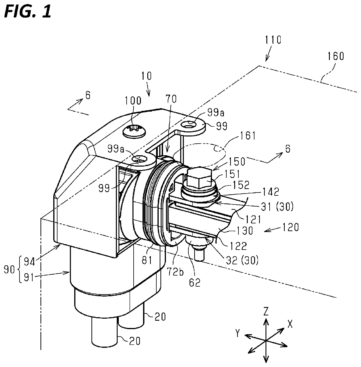
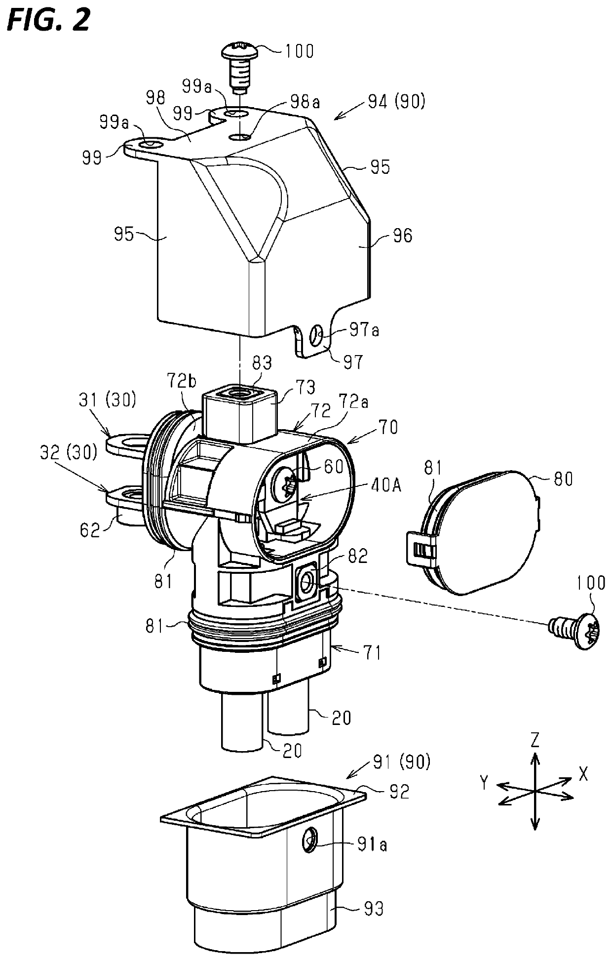
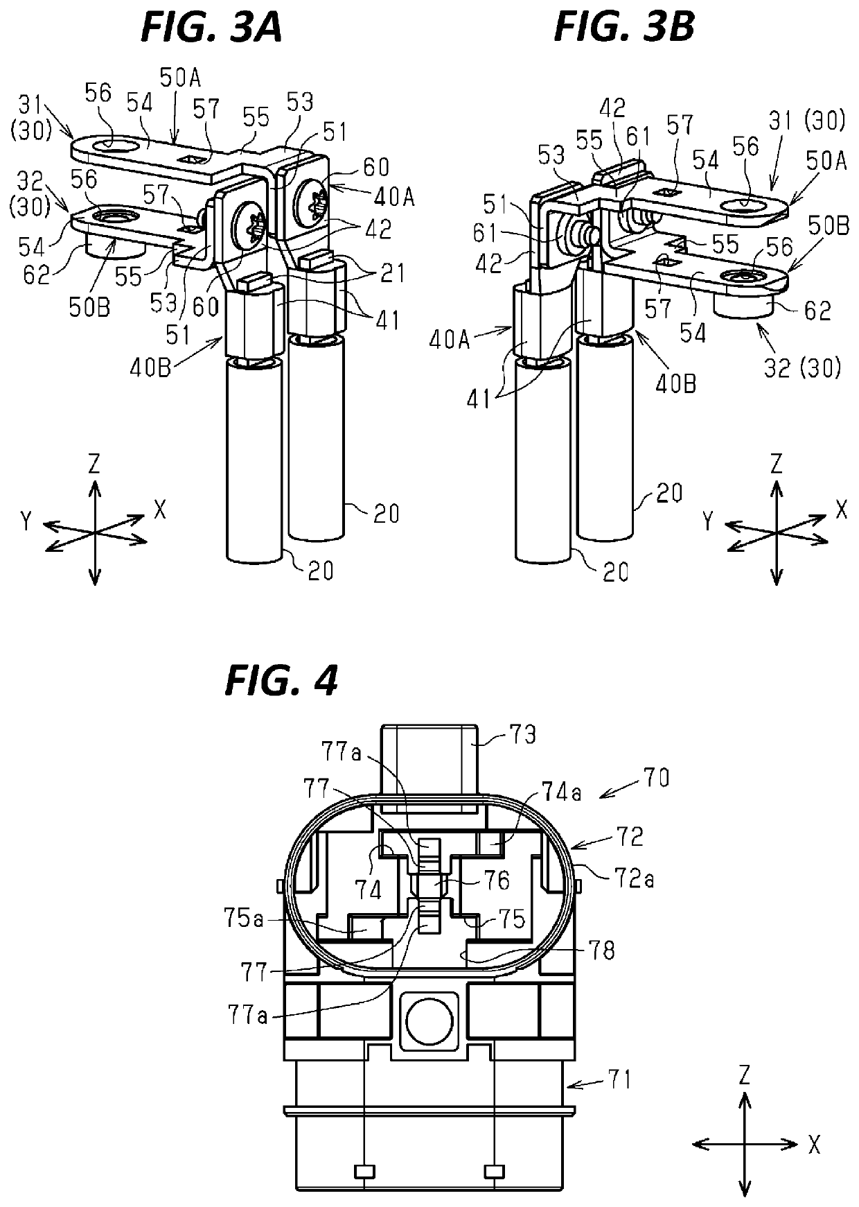
[0025]Hereinafter, one embodiment is described with reference to FIGS. 1 to 7.

[0026]As shown in FIGS. 1 to 3B, a connector 10 includes connection terminals 30 to be respectively connected to ends 21 of two wires 20 extending side by side and a housing 70 for accommodating these connection terminals 30 separated from each other with tip parts of the connection terminals 30 projecting out. Note that an arrangement direction of the twire 20 and an extending direction of the tip parts of the connection terminals 30 are orthogonal.

[0027]In the following description, the arrangement direction of the wires 20, the extending direction of the tip parts of the connection terminals 30 and a direction orthogonal to both the arrangement direction and the extending direction are referred to as an arrangement direction X, an extending direction Y and an orthogonal direction Z.

[0028]In this embodiment, each connection terminal 30 of the connector 10 is, for example, electrically connected to a term...


PUM


Abstract

A connector 10 includes two connection terminals 30 to be respectively connected to ends of two wires 20 extending side by side and having through holes in tip parts, and a housing 70 for accommodating the two connection terminals 30 separated from each other with the respective tip parts caused to project out. The tip parts of the two connection terminals 30 are overlapped each other while being spaced apart in an orthogonal direction Z, and the through holes of the two connection terminals 30 are located on the same axis along the orthogonal direction Z.

Description

TECHNICAL FIELD[0001]The present invention relates to a connector and a connector connection structure.BACKGROUND[0002]Patent Document 1 discloses a connector to be connected to a device of a vehicle. The connector described in Patent Document 1 includes two L-shaped terminals respectively connected to ends of two wires, a separate housing into which the both wires are inserted and which includes a service hole used to mount the both L-shaped terminals from front, and a service cover for closing the service hole.[0003]In the case of connecting the above connector to the device, the two wires connected to the L-shaped terminals are inserted into the separate housing and the two L-shaped terminals are arranged in the service hole. Subsequently, the service hole is closed by the service cover and tip parts of the two L-shaped terminals are caused to project from the service cover. Then, bolts are inserted through bolt holes formed in the tip parts of the two L-shaped terminals and resp...

Claims


Application Information

Patent Timeline
IPC IPC(8): H01R9/11
CPCH01R9/11H01R11/05H01R2201/26H01R11/12H01R13/4223H01R13/6593H01R4/30H01R4/308H01R9/223
Inventor KITAOKA, KENICHIMUKUNO, JUNICHI
Owner AUTONETWORKS TECH LTD
Why Eureka
Try Eureka