Image display apparatus and image display method

Inactive Publication Date: 2010-01-07
FUNAI ELECTRIC CO LTD
View PDF3 Cites 19 Cited by
  • Summary
  • Abstract
  • Description
  • Claims
  • Application Information

AI Technical Summary

Benefits of technology

[0010]Conventionally, these detectors have been arranged separately in a laser projector. This has led to an incr

Problems solved by technology

This has led to an increase in the number of parts, and thus an incr

Method used


Image

  • Image display apparatus and image display method
  • Image display apparatus and image display method
  • Image display apparatus and image display method

Examples


Example

[0032]Hereinafter, an embodiment of the present invention will be described with reference to the drawings. In the description below, identical parts will be designated by the same reference numerals. Since their names and functions are also identical, the detailed description thereof will not be repeated.

[0033][1. Overall Configuration of Apparatus]

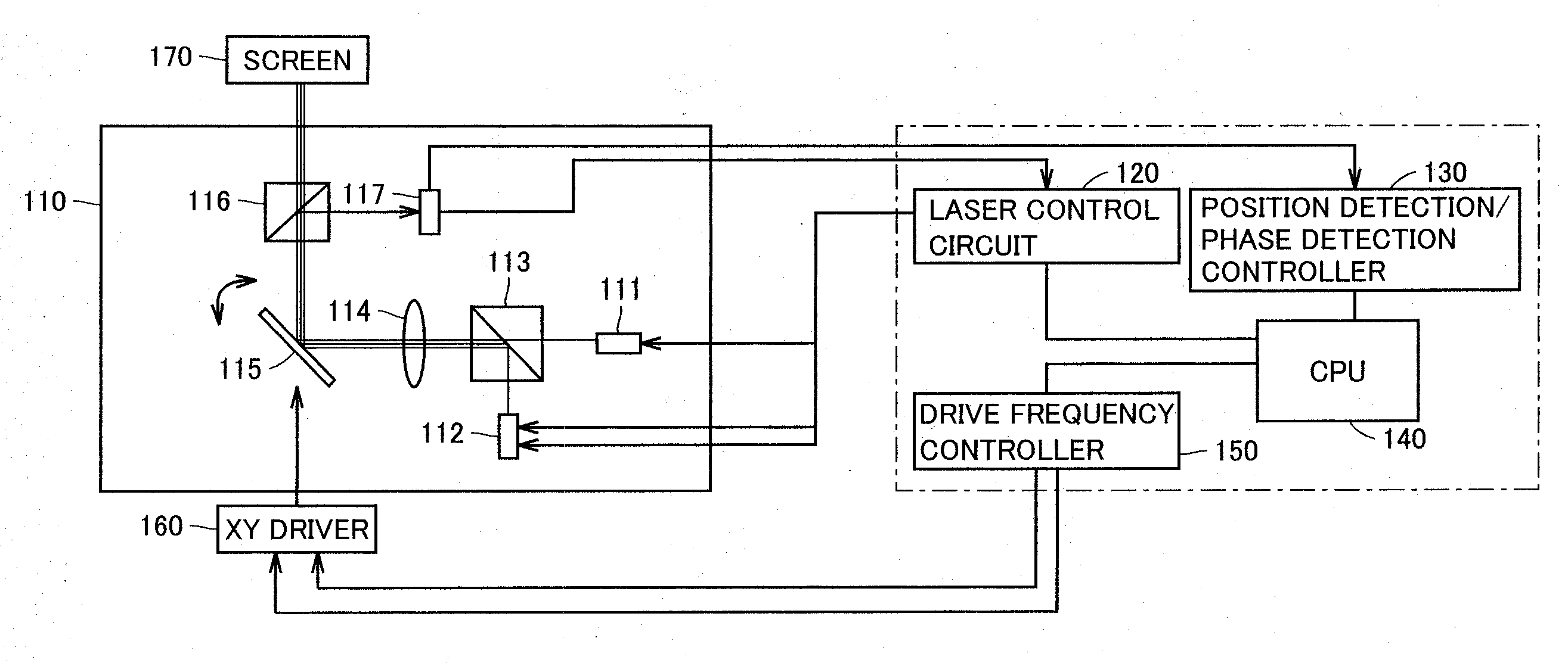
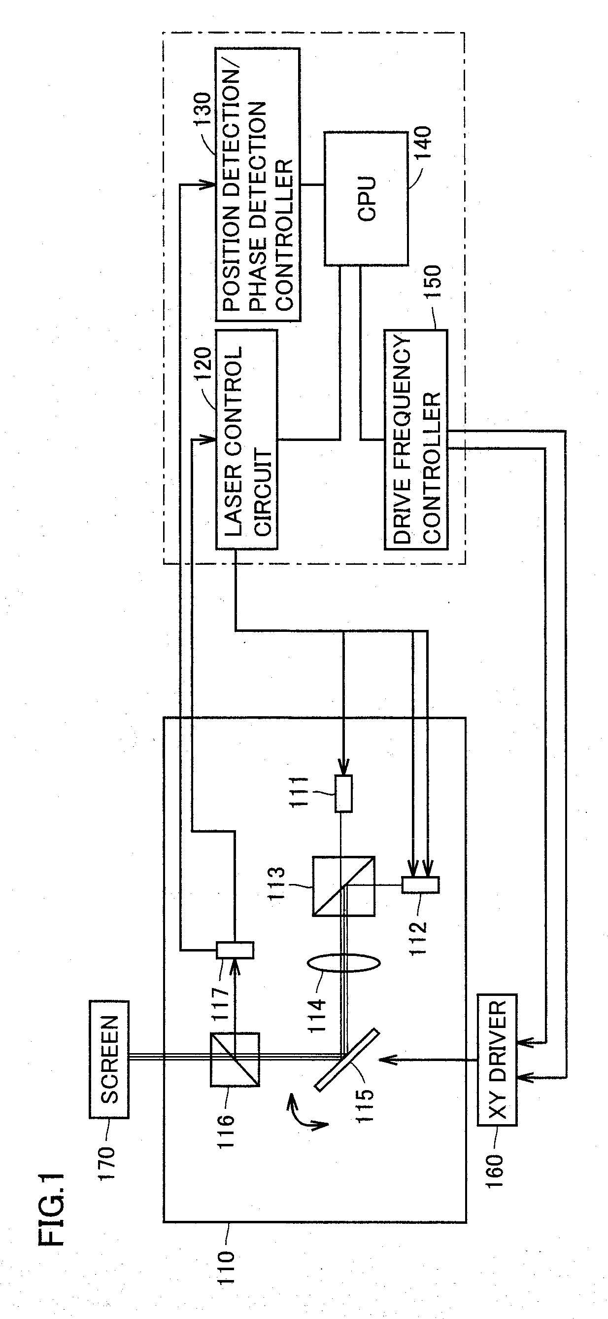
[0034]Referring to FIG. 1, a configuration of an image display apparatus 100 in accordance with the present embodiment will be described. FIG. 1 is a block diagram showing a configuration of image display apparatus 100 in accordance with the present embodiment.

[0035]Image display apparatus 100 is a so-called laser projector for displaying an image on a projection surface by applying a laser beam onto the projection surface. Image display apparatus 100 includes an optical system 110, a laser control circuit 120, a position detection / phase detection controller 130, a CPU (Central Processing Unit) 140, a drive frequency controller 150, and ...


PUM


Abstract

A detection surface of an optical detector is divided into regions C, E, F, G, and H. The optical detector outputs detection signals corresponding to the amounts of light incident on the respective regions. A position detection controller calculates an image projection position based on timing at which a laser beam is incident on region C. A laser control circuit adjusts the intensity of the laser beam emitted by a laser based on laser beam intensities detected in regions E to H arranged around region C.

Description

BACKGROUND OF THE INVENTION[0001]1. Field of the Invention[0002]The present invention relates to an image display apparatus and an image display method for displaying an image by projecting light onto a projection surface. Particularly, the present invention relates to an image display apparatus and an image display method for displaying an image by projecting a laser beam onto a projection surface.[0003]2. Description of the Background Art[0004]In recent years, development of laser projectors for displaying an image by projecting a laser beam onto a projection surface such as a screen has advanced. To display an image appropriately with a laser projector, it is important to detect the intensity of a laser beam emitted by a laser and the position of a scanning element scanning the laser beam on a projection surface, and to determine scanning timing.[0005]Patent Document 1 (Japanese Patent Laying-Open No. 2007-147728) discloses an image display apparatus including an optical detector...

Claims


Application Information

Patent Timeline
IPC IPC(8): H04N5/64
CPCG09G3/02H04N9/3129G09G2320/0233
Inventor NISHIOKA, KENHIRANO, ATSUYANAGASHIMA, KENJIMURAYAMA, MANABU
Owner FUNAI ELECTRIC CO LTD
Why Eureka
Try Eureka