Motor drive circuit mounting structure and electric compressor

Inactive Publication Date: 2009-04-16
DENSO CORP
View PDF1 Cites 24 Cited by
  • Summary
  • Abstract
  • Description
  • Claims
  • Application Information

AI Technical Summary

Benefits of technology

[0008]To cope with this problem, a shield plate, for example, may be used to shield the low-voltage circuit from the electromagnetic wave at the sacrifice of an increased number of parts and a higher cost.
[0009]In view of this situation, th

Problems solved by technology

In the electric compressor described above, electromagnetic noise is generated by the switching operation of each semiconductor switching device.
The low-voltage circuit may be adversely affected by the electromagnetic noise generated fro

Method used


Image

  • Motor drive circuit mounting structure and electric compressor
  • Motor drive circuit mounting structure and electric compressor
  • Motor drive circuit mounting structure and electric compressor

Examples


Example

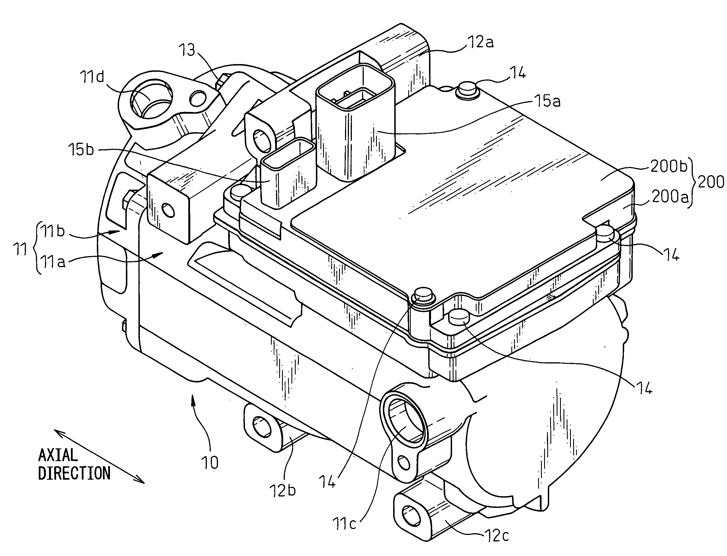
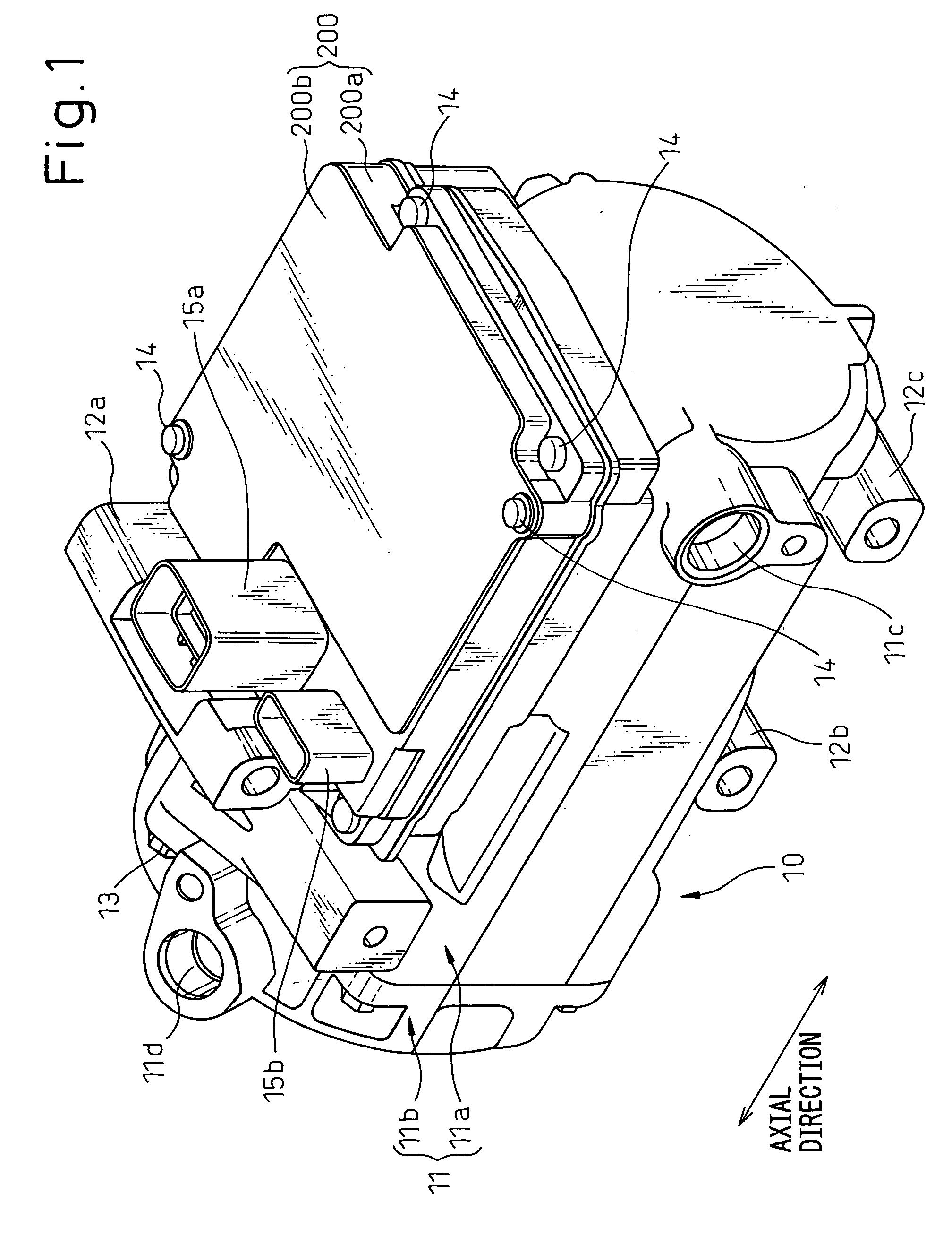
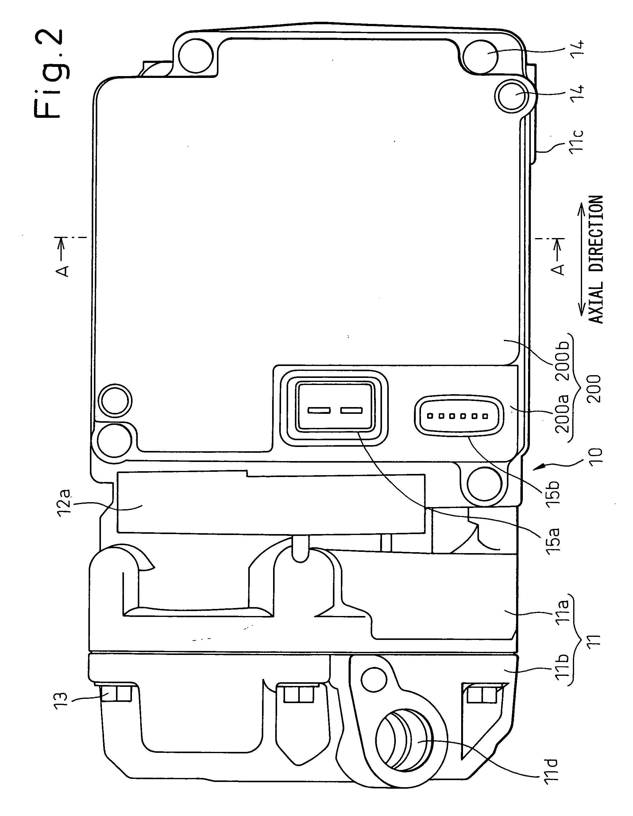
[0071]The electric compressor for automobiles according to the first embodiment of the invention is shown in FIGS. 1 to 3. FIG. 1 is a perspective view of the automotive electric compressor, FIG. 2 a top plan view of the automotive electric compressor, FIG. 3 a front view of the automotive electric compressor, and FIG. 4 is a left side view of the automotive electric compressor.

[0072]The automotive electric compressor 10 according to this embodiment, as shown in FIG. 1, together with a condenser, an expansion valve and an evaporator, makes up a well-known refrigeration cycle system for circulating the refrigerant of the automotive air conditioning system.

[0073]The automotive electric compressor 10, as shown in FIG. 1, has a compressor housing 11. The compressor housing 11 is configured of a cylindrical housing body 11a and a lid portion 11b. The cylindrical housing body 11a is formed with an opening exposed to a first axial end, and the lid portion 11b is coupled to the cylindrical ...

Example

Second Embodiment

[0125]The first embodiment described above refers to a case in which the depressions 11s and 11v are formed on the opposed sides of the flat mounting portion 11t in the orthogonal direction. On the other hand, according to the second embodiment, as shown in the sectional view of FIG. 10, the depressions 11s and 11v are formed on the opposed sides of the flat mounting portion 11t in the axial direction. Specifically, the depressions 11s and 11v are formed on the two axial sides of the stator 320 included in the solid portion of the compressor housing

[0126]As a result, the electromagnetic coil 71a and the capacitor 71b are arranged at the first axial end of the stator 320, while the sub-communication circuit 50a is arranged at the second axial end of the stator 320.

Example

Third Embodiment

[0127]The first embodiment described above refers to a case in which the depressions 11s and 11v are formed by being depressed from the flat mounting portion 11t side. As an alternative, according to the present embodiment, the depressions 11s and 11v are formed as shown in FIGS. 11 and 12.

[0128]FIG. 11 is a sectional view showing the depressions 11s and 11v as viewed along the axial direction, and FIG. 12 a view showing the depressions 11s and 11v taken from above with the sub-communication circuit 50a, etc. not accommodated therein.

[0129]The depression 11s is formed at the corner formed by the side surface 11q making up the outer wall of the compressor housing 11 and the flat mounting portion 11t. The side surface 11q and the flat mounting portion 11t are formed orthogonally to each other. The depression 11s is depressed from the side surface 11q and the flat mounting portion 11t at the same time.

[0130]The depression 11v is formed at the corner formed by the side s...


PUM


Abstract

A mounting structure of a motor drive circuit and an electric compressor are disclosed. A sub-communication circuit 50a of a communication circuit 50 is accommodated in a depression 11v of a compressor housing 11. Semiconductor switching devices S1 to S6 are arranged on the flat mounting portion 11t of the compressor housing 11, i.e. on the outside of the depression 11v. As a result, the sub-communication circuit 50a can be isolated from the semiconductor switching devices S1 to S6. Although the switching operation of the semiconductor switching devices S1, S2, . . . , S6 generates electromagnetic noise, since the sub-communication circuit 50a is accommodated in the depression 11v, the sub-communication circuit 50a receives less electromagnetic noise.

Description

BACKGROUND OF THE INVENTION[0001]1. Field of the Invention[0002]This invention relates to a mounting structure of a motor drive circuit and an electric compressor.[0003]2. Description of the Related Art[0004]A conventional electric compressor is configured of a compression unit accommodated in a housing, a three-phase AC motor accommodated in the housing to drive the compression unit and a motor drive circuit mounted on the outer wall of the housing to drive the three-phase AC motor (refer to, for example, Japanese Unexamined Patent Publication No. 2003-262187).[0005]Generally, the motor drive circuit of an electric compressor includes a high-voltage circuit having six semiconductor switching devices inserted between two power terminals of a high-voltage power supply and a low-voltage circuit supplied with power from the a low-voltage power supply to drive each semiconductor switching device.[0006]With each semiconductor switching device controlled by the low-voltage circuit, the hi...

Claims


Application Information

Patent Timeline
IPC IPC(8): H02K5/00
CPCH02K11/0073H02K5/225H02K11/33
Inventor SUMI, TOMOYUKIMATSUKI, TATSUHIRO
Owner DENSO CORP
Why Eureka
Try Eureka