Method of manufacturing a piezoelectric device

Inactive Publication Date: 2005-12-20
SEIKO EPSON CORP
View PDF41 Cites 25 Cited by
  • Summary
  • Abstract
  • Description
  • Claims
  • Application Information

AI Technical Summary

Benefits of technology

[0010]The present invention has an object to solve the problems mentioned above in the conventional

Problems solved by technology

However, the glass lid requires a high material cost and also a high cost for cutting the lid from a glass substrate into a rectangular shape of the lid at a high accuracy, resulting in a high cost of the piezo-electric resonator.
Fine dust produced from the glass lid exerts an a

Method used


Image

  • Method of manufacturing a piezoelectric device
  • Method of manufacturing a piezoelectric device
  • Method of manufacturing a piezoelectric device

Examples


first embodiment

(First Embodiment)

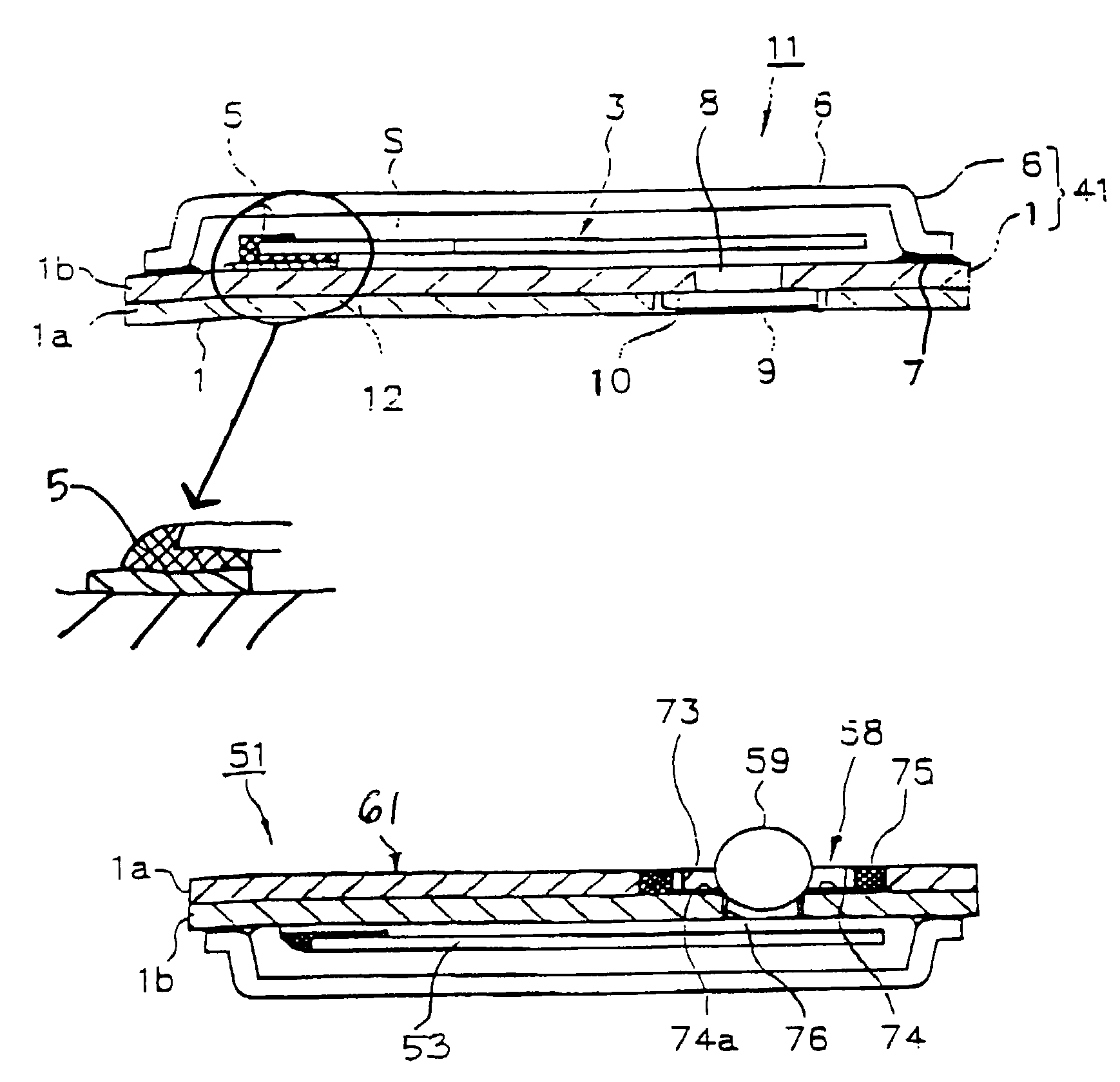
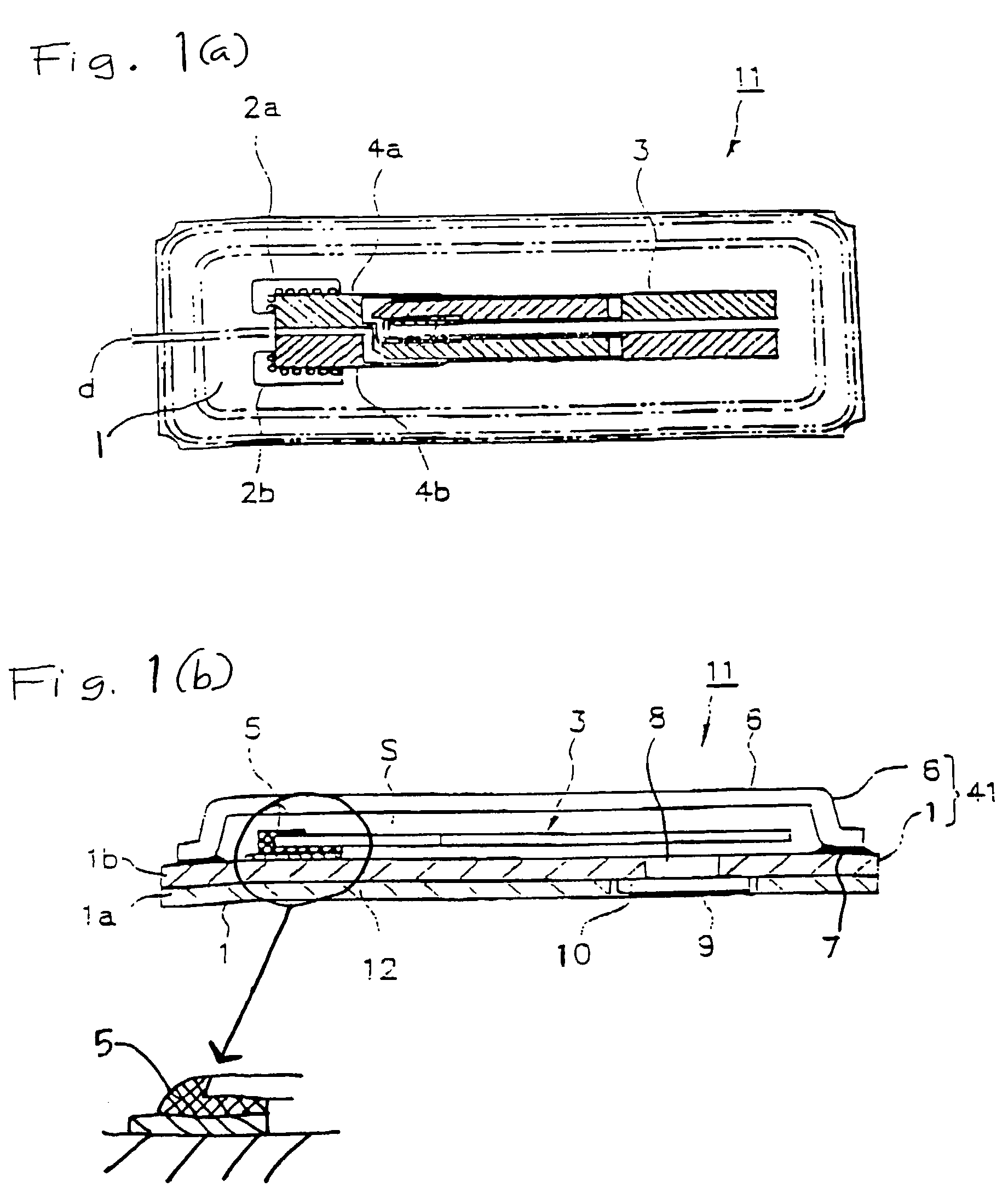
[0081]FIG. 1(a) is a plan view of the piezo-electric resonator 11 of this embodiment, and FIG. 1(b) is a front view of the piezo-electric resonator 11.

[0082]As shown in these drawings, metallized electrode sections 2a and 2b having the surface plated with Ni and Au are formed at an interval d on a base 1, the base being formed by laminating two ceramic substrates 1a and 1b. Electrode sections 4a and 4b of, for example, a tuning fork type quartz resonator element 3, serving as piezo-electric resonator elements and having driving metal electrodes formed on the surfaces thereof are aligned with, and mounted on, the electrode sections 2a and 2b of this base 1. The electrode sections 4a and 4b and electrode sections 2a and 2b are electrically connected and secured with a conductive adhesive 5. Then, the metal lid 6 is aligned with the base 1. A first sealing step is carried out by melting a sealing material 7 using a beam irradiating device serving as heater such as a l...

second embodiment

(Second Embodiment)

[0095]FIG. 4 illustrates a piezo-electric resonator 42 of another embodiment of the invention. The components of this piezo-electric resonator 42 corresponding to those in the first embodiment are assigned the same reference numerals, and description which would be a duplication is omitted here. The piezo-electric resonator 42 is different from that in the first embodiment in that a ceramic lid 31 is used in place of the metal lid 6 shown in FIG. 1(b). The piezo-electric resonator 42 of the second embodiment can therefore bring about the same advantages as those in the first embodiment.

third embodiment

(Third Embodiment)

[0096]FIG. 5 illustrates a piezo-electric resonator 43 of a further embodiment of the invention. The components of this piezo-electric resonator 43 corresponding to those in the second embodiment are assigned the same reference numerals, and description which would lead to duplication is omitted here. The piezo-electric resonator 43 is different from that in the second embodiment in that an opening 32 is formed in the lid 31 shown in FIG. 4. The piezo-electric resonator 43 of the third embodiment can therefore bring about the same advantages as those in the first and the second embodiments.


PUM

PropertyMeasurementUnit
Diameteraaaaaaaaaa
Sizeaaaaaaaaaa

Abstract

A compact and thin piezo-electric resonator is provided having a high air-tightness and available at a low cost, in which a piezo-electric resonator element is provided in a housing having a structure which permits adjustment of the frequency after sealing the housing. Further, a surface-mounting type piezo-electric resonator is provided, in which a piezo-electric resonator element is provided in a housing, having a structure which permits frequency adjustment through an opening provided in a base or a lid forming the housing.

Description

[0001]This is a Continuation-in-Part of application Ser. No. 09 / 120,860 filed Jul. 23, 1998 now abandoned. The entire disclosure of the prior application(s) is hereby incorporated by reference herein in its entirety.BACKGROUND OF THE INVENTION[0002]1. Field of Invention[0003]The present invention relates to a piezo-electric resonator having a piezo-electric resonator element provided in a housing, and a manufacturing method thereof.[0004]2. Description of Related Art[0005]There has recently been a remarkable tendency directed toward a smaller and thinner size of mobile communication devices such as an HDD (hard disk drive), a mobile computer, and compact information devices such as an IC card, a portable telephone, car telephone and a paging system. Achievement of a smaller and thinner size is also demanded for piezo-electric devices such as a piezo-electric resonator used in these communication devices. There is simultaneously a requirement for a surface mounting type piezo-electri...

Claims


Application Information

Patent Timeline
IPC IPC(8): H01L41/053H03H9/10H03H9/21H04R17/00
CPCH01L41/053H03H9/1021H03H9/21H04R17/00Y10T29/49128Y10T29/49156Y10T29/49004Y10T29/4913Y10T29/49126Y10T29/49144Y10T29/42H10N30/88
Inventor KIKUSHIMA, MASAYUKIMORITA, YOSHIO
Owner SEIKO EPSON CORP
Why Eureka
Try Eureka