Inspection device of a tape reel

Inactive Publication Date: 2006-04-20
FUJIFILM CORP
View PDF3 Cites 0 Cited by
  • Summary
  • Abstract
  • Description
  • Claims
  • Application Information

AI Technical Summary

Benefits of technology

[0015] Moreover, the positioning device that performs positioning by grasping the flange by the clamp poses furthe

Problems solved by technology

However, in order to improve the accuracy of the positioning by tight engagement of the hub and the disk, a problem is involved therein in such a way that it is easily damaged by an unreasonable handling.
However, in the conventional needle contact type measuring method, error of Am order is generated by slight contact pressure of the probe needle, thereby involving a problem that the size of the μm order of an object to be measured cannot be measured.
Moreover, more problems are involved therein in such a way that an object to be measured is damaged by the probe which is contacted with the object to be measured one by one, or time required for measurement is longer compared with an optical measuring method that measures in an un-contacting state.
In addition, when a miniaturized tape reel is inspected in order to hold a tape with narrow width, distance between flanges becomes short.
Thereby it becomes difficult to insert the probe between flanges.
Here, a method for inserting a reflective sensor or a mirror between the flanges 42 and 43 is conceivable, however involving a problem that the structure of the inspection devic

Method used


Image

  • Inspection device of a tape reel
  • Inspection device of a tape reel
  • Inspection device of a tape reel

Examples


Example

[0034]FIG. 1 is a perspective view showing an example of the tape reel.

[0035]FIG. 2 is a sectional view taken along the line A-A in FIG. 1.

[0036]FIG. 3 is an exploded perspective view for explaining a method for manufacturing the tape reel of FIG. 1.

[0037]FIG. 4 is a plan view showing a constitution of an inspection device of the tape reel.

[0038]FIG. 5A is a view showing a state in which parallel lights R1, R2 are irradiated onto the inner surface of the lower flange and the upper flange. FIG. 5B is a view showing a state in which parallel lights R3, R4 are irradiated onto the inner surface of the lower flange and the upper flange.

[0039]FIG. 6A is a front view showing a constitution of a shielding plate, FIG. 6B is a side view showing a state in which only parallel light is irradiated in the vicinity of the inner surface of the flange of the tape reel, from the lights irradiated from a light projector using a shielding plate shown in FIG. 6A.

[0040]FIG. 7A is an image of the pa...


PUM

PropertyMeasurementUnit
Pressureaaaaaaaaaa
Speedaaaaaaaaaa
Distanceaaaaaaaaaa

Abstract

An inspection device of a tape reel comprises a first inspection device 10 consisting of a light projector 11, a mirror 12, and a light receiver 13, a second inspection device 20 consisting of a light projector 21, a mirror 22, and a light receiver 23, and a rotator 30 that rotates a tape reel 40, and parallel lights R1, R2 irradiated from the light projector 11 are reflected by the mirror 12, to be made incident on inner surfaces of flanges 42, 43 of the tape reel 40, whereas parallel lights R3, R4 irradiated from the light projector 21 are reflected by the mirror 22 to be made incident on the inner surfaces of the flanges 42, 43 of the tape reel 40, and parallel lights R1 to R4 that pass the inner surfaces of the flanges 42, 43 are received by the light receiver 13 or the light receiver 23. Thereby, an inspection device capable of inspecting a position of each flange of the tape reel, distance between flanges, and an inclined angle of each flange in a un-contact state accurately at high speed, an inspection method for the same, and a positioning device of a member to be positioned capable of positioning the position of the flange accurately are provided.

Description

[0001] This is a divisional of application Ser. No. 10 / 601,677 filed Jun. 24, 2003, the entire disclosure of the prior application, application Ser. No. 10 / 601,677 is hereby incorporated by reference.DETAILED DESCRIPTION OF THE INVENTION [0002] 1. Technical Field of the Invention [0003] The present invention relates to an inspection device of a tape reel and an inspection method for the same, especially relates to an inspection device for inspecting a dimension accuracy of a flange in a tape reel in which a pair of disk-shaped flanges are fixed in a mutually facing manner on both ends of a cylindrical hub, and an inspection method for the same. [0004] 2. Background of the Invention 
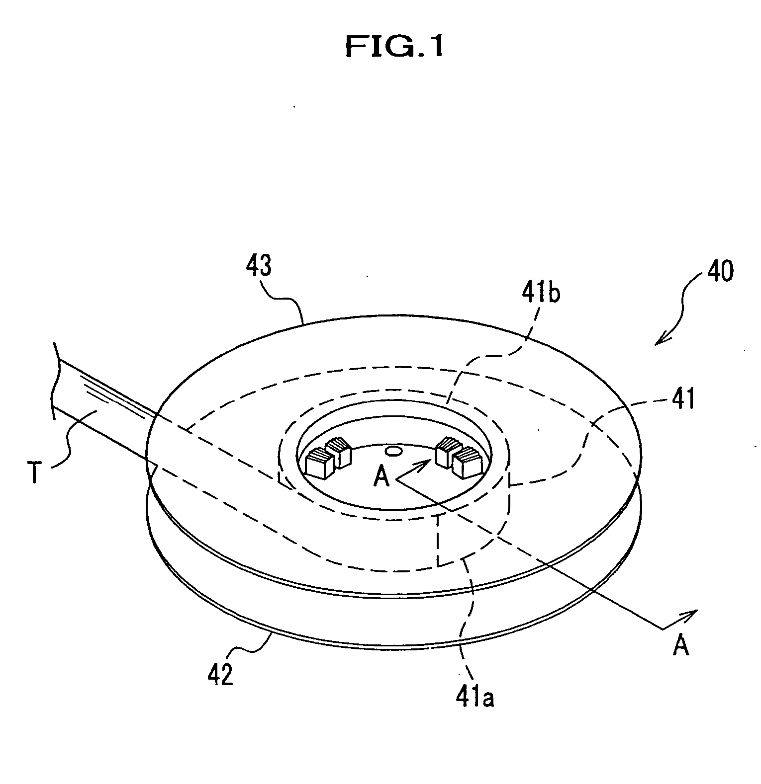
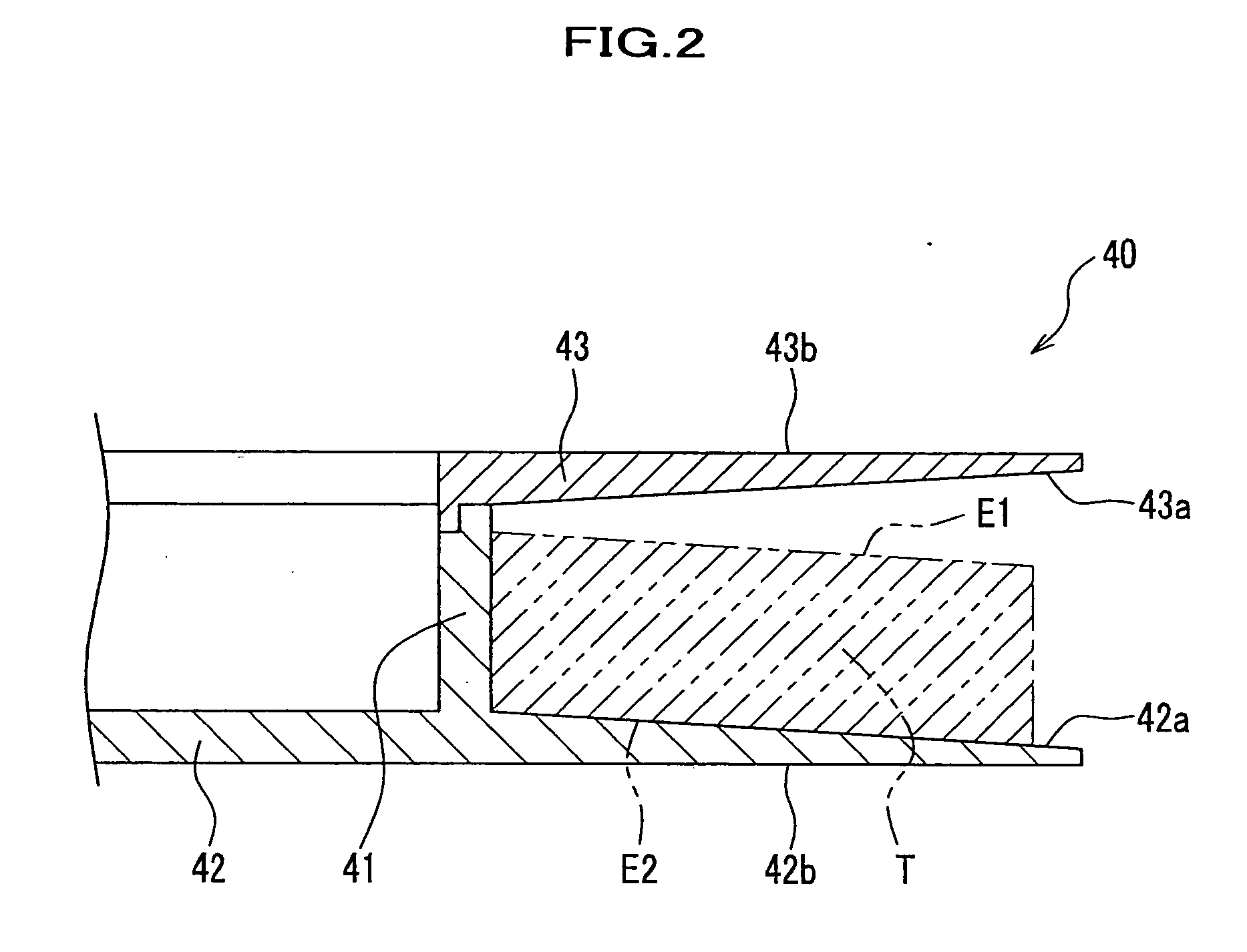
[0005] Conventionally, a magnetic tape serving as a magnetic recording medium is widely used as a recording medium used for other record reproducing devices such as an audio device and a video device. Generally various films, such as a magnetic tape, a movie film, and an X ray film, are wound on the tape ...

Claims


Application Information

Patent Timeline
IPC IPC(8): G01B11/14B65H23/02G01B11/00G11B15/60G11B23/037G11B23/04G11B33/10
CPCB65H23/0216B65H2301/41368B65H2511/24B65H2553/414B65H2701/18444B65H2701/18483G01B11/00G11B15/602G11B23/037G11B23/044G11B33/10B65H2220/03
Inventor HAYASHI, YOICHI
Owner FUJIFILM CORP
Why Eureka
Try Eureka