Photoelectric composite wiring module

Inactive Publication Date: 2013-08-15
HITACHI METALS LTD
View PDF14 Cites 25 Cited by
  • Summary
  • Abstract
  • Description
  • Claims
  • Application Information

AI Technical Summary

Benefits of technology

[0009]In the photoelectric composite wiring module described in JP-A-2011-53269, since the surface of the printed-circuit board on which the groove for the optical transmission line and the groove for the electric wiring are formed is different from the surface mounting the optical transmitter module or the optical receiver module, work of receiving and fixing the optical fiber and the electric wiring into the groove for the optical transmission line and

Problems solved by technology

Thus, it is necessary to flip over the printed-circuit board, e.g., after mounting the optical transmitter module or the optical receiv

Method used


Image

  • Photoelectric composite wiring module
  • Photoelectric composite wiring module
  • Photoelectric composite wiring module

Examples


Example

[0037]A structural example of a photoelectric composite wiring module in the embodiment of the invention will be described below in reference to FIGS. 1A to 7.

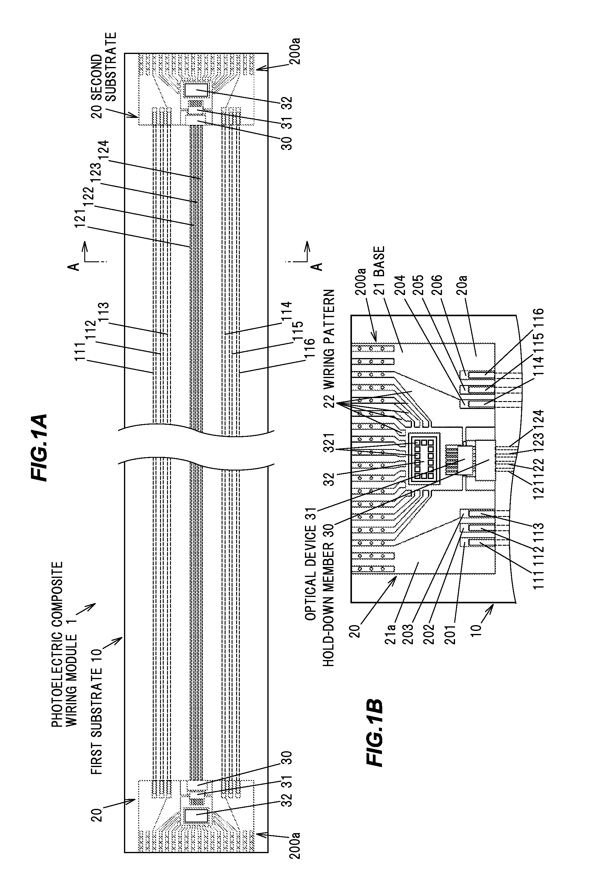
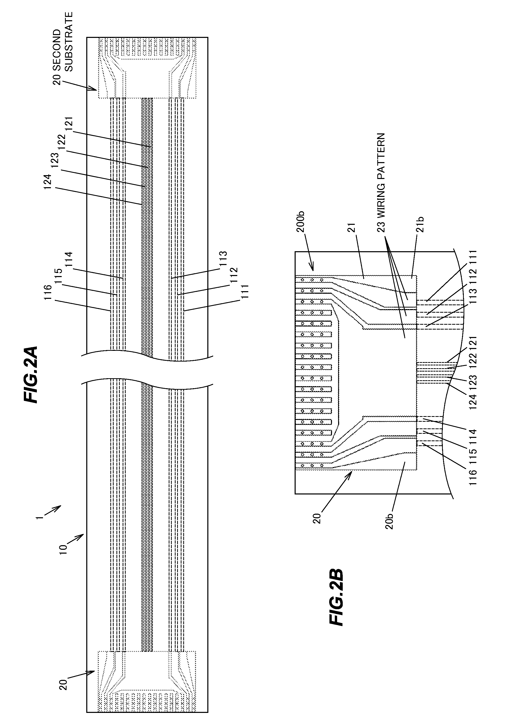
[0038]FIGS. 1A and 1B are plan views showing a photoelectric composite wiring module 1 in the present embodiment as viewed from one surface side. FIGS. 2A and 2B are plan views showing the photoelectric composite wiring module 1 shown in FIG. 1 as viewed from another surface side.

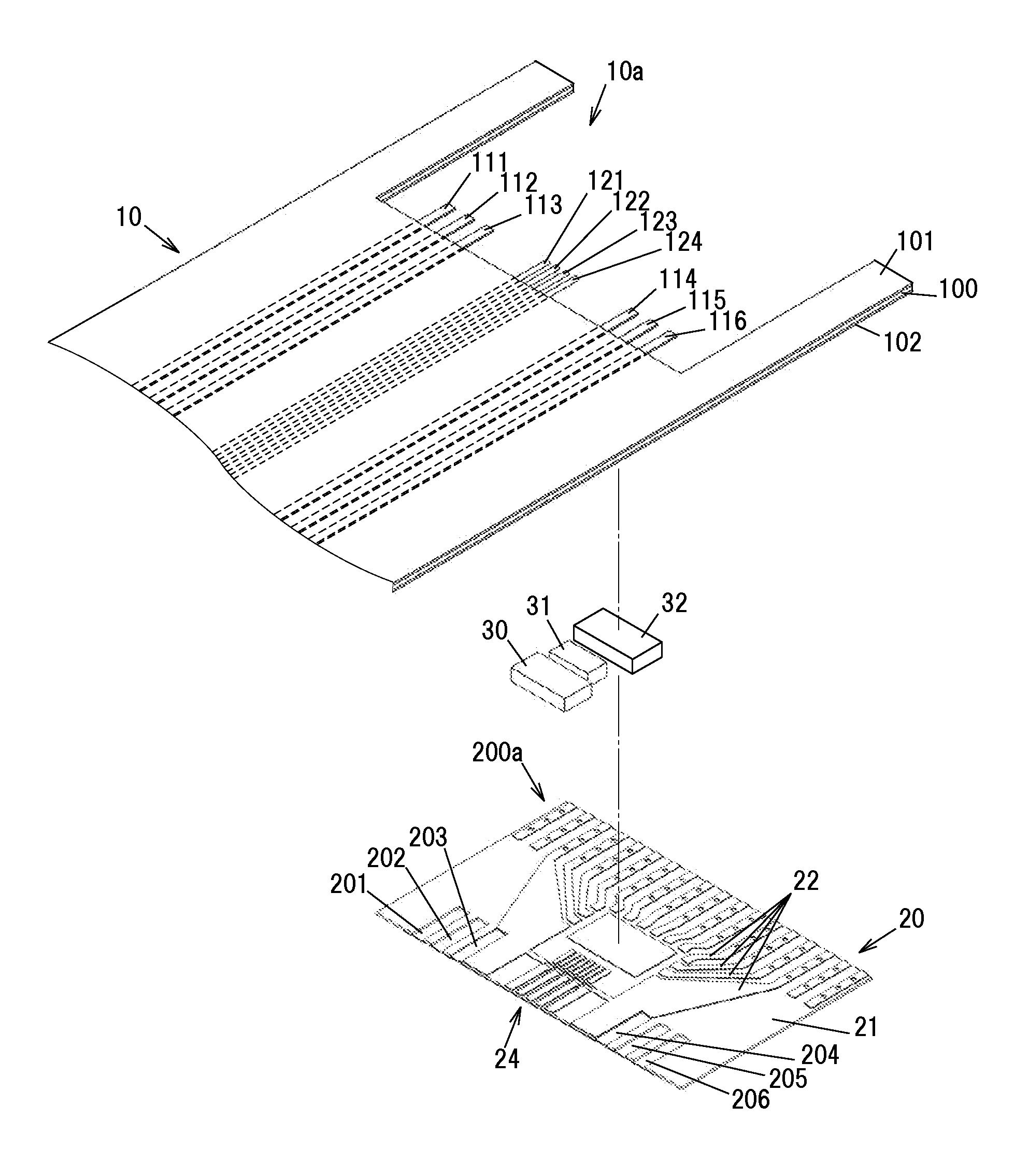
[0039]The photoelectric composite wiring module 1 is provided with a long first substrate 10, a pair of second substrates 20 connected to both end portions of the first substrate 10, and an optical device 31 and a semiconductor circuit element 32 which are mounted on each second substrate 20.

[0040]The first substrate 10 is a flat cable with flexibility having first to sixth conductive lines 111 to 116 and first to fourth optical fibers 121 to 124 provided along a longitudinal direction thereof. The first to fourth optical fibers 121 to 124 are optical...


PUM


Abstract

A photoelectric composite wiring module includes a flexible first substrate including a conductive line and an optical fiber mounted thereon along a longitudinal direction thereof, a second substrate including a recessed portion formed thereon to receive the conductive line and the optical fiber that protrude from an end portion of the first substrate, and an optical device mounted on the second substrate and optically coupled to the optical fiber. The recessed portion includes an opening on a mounting surface side of the second substrate to mount the optical device.

Description

[0001]The present application is based on Japanese patent application No. 2012-030680 filed on Feb. 15, 2012, the entire contents of which are incorporated herein by reference.BACKGROUND OF THE INVENTION[0002]1. Field of the Invention[0003]The invention relates to a photoelectric composite wiring module which transmits signals through a conductive line and an optical fiber.[0004]2. Description of the Related Art[0005]A conventional photoelectric composite wiring module is known in which a flat cable having an optical transmission line and an electric wiring is optically and electrically connected to a pair of printed-circuit boards at both longitudinal ends (see JP-A-2011-53269).[0006]In the photoelectric composite wiring module described in JP-A-2011-53269, an optical transmitter module composed of a light-emitting element and a driver IC is mounted on one of the paired printed-circuit boards and an optical receiver module composed of a light-receiving element and a preamplifier IC...

Claims


Application Information

Patent Timeline
IPC IPC(8): G02B6/12
CPCG02B6/12G02B6/428G02B6/4202G02B6/4214G02B6/4239H05K2201/10121G02B6/43G02B6/4416H05K1/118H05K2201/0108G02B6/4245
Inventor YU, JUHYUNYASUDA, HIROKIHIRANO, KOUKIISHIKAWA, HIROSHI
Owner HITACHI METALS LTD
Why Eureka
Try Eureka